TOP Contributors

  1. MIKROE (2784 codes)
  2. Alcides Ramos (385 codes)
  3. Shawon Shahryiar (307 codes)
  4. jm_palomino (118 codes)
  5. Bugz Bensce (97 codes)
  6. S P (73 codes)
  7. dany (71 codes)
  8. MikroBUS.NET Team (35 codes)
  9. NART SCHINACKOW (34 codes)
  10. Armstrong Subero (27 codes)

Most Downloaded

  1. Timer Calculator (139847 times)
  2. FAT32 Library (72210 times)
  3. Network Ethernet Library (57392 times)
  4. USB Device Library (47740 times)
  5. Network WiFi Library (43364 times)
  6. FT800 Library (42700 times)
  7. GSM click (29980 times)
  8. mikroSDK (28442 times)
  9. PID Library (26989 times)
  10. microSD click (26398 times)
Libstock prefers package manager

Package Manager

We strongly encourage users to use Package manager for sharing their code on Libstock website, because it boosts your efficiency and leaves the end user with no room for error. [more info]

< Back
mikroSDK Library

POT 2 click

Rating:

5

Author: MIKROE

Last Updated: 2019-02-04

Package Version: 1.0.0.0

mikroSDK Library: 1.0.0.0

Category: Measurements

Downloaded: 4115 times

Not followed.

License: MIT license  

POT 2 click is a Click board with the accurate selectable reference voltage output. By utilizing a multi-turn precision potentiometer, this Click board can provide very accurate voltage output on the AN pin of the mikroBUS.

No Abuse Reported

Do you want to subscribe in order to receive notifications regarding "POT 2 click" changes.

Do you want to unsubscribe in order to stop receiving notifications regarding "POT 2 click" changes.

Do you want to report abuse regarding "POT 2 click".
  • mikroSDK Library 2.0.0.0
  • Comments (0)
DOWNLOAD LINK RELATED COMPILER CONTAINS
mikroBasic PRO for ARM
  • lib
  • src
  • exa
  • hlp
  • hex
  • sch
  • pcb
  • doc
mikroBasic PRO for AVR
  • lib
  • src
  • exa
  • hlp
  • hex
  • sch
  • pcb
  • doc
mikroBasic PRO for dsPIC30/33 & PIC24
  • lib
  • src
  • exa
  • hlp
  • hex
  • sch
  • pcb
  • doc
mikroBasic PRO for FT90x
  • lib
  • src
  • exa
  • hlp
  • hex
  • sch
  • pcb
  • doc
mikroBasic PRO for PIC
  • lib
  • src
  • exa
  • hlp
  • hex
  • sch
  • pcb
  • doc
mikroBasic PRO for PIC32
  • lib
  • src
  • exa
  • hlp
  • hex
  • sch
  • pcb
  • doc
mikroC PRO for ARM
  • lib
  • src
  • exa
  • hlp
  • hex
  • sch
  • pcb
  • doc
mikroC PRO for AVR
  • lib
  • src
  • exa
  • hlp
  • hex
  • sch
  • pcb
  • doc
mikroC PRO for dsPIC30/33 & PIC24
  • lib
  • src
  • exa
  • hlp
  • hex
  • sch
  • pcb
  • doc
mikroC PRO for FT90x
  • lib
  • src
  • exa
  • hlp
  • hex
  • sch
  • pcb
  • doc
mikroC PRO for PIC
  • lib
  • src
  • exa
  • hlp
  • hex
  • sch
  • pcb
  • doc
mikroC PRO for PIC32
  • lib
  • src
  • exa
  • hlp
  • hex
  • sch
  • pcb
  • doc
mikroPascal PRO for ARM
  • lib
  • src
  • exa
  • hlp
  • hex
  • sch
  • pcb
  • doc
mikroPascal PRO for AVR
  • lib
  • src
  • exa
  • hlp
  • hex
  • sch
  • pcb
  • doc
mikroPascal PRO for dsPIC30/33 & PIC24
  • lib
  • src
  • exa
  • hlp
  • hex
  • sch
  • pcb
  • doc
mikroPascal PRO for FT90x
  • lib
  • src
  • exa
  • hlp
  • hex
  • sch
  • pcb
  • doc
mikroPascal PRO for PIC
  • lib
  • src
  • exa
  • hlp
  • hex
  • sch
  • pcb
  • doc
mikroPascal PRO for PIC32
  • lib
  • src
  • exa
  • hlp
  • hex
  • sch
  • pcb
  • doc

mikroSDK Library Blog

POT 2 click

POT 2 click

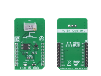
Native view of the POT 2 click board.

View full image
POT 2 click

POT 2 click

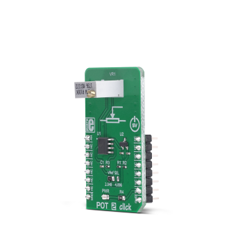
Front and back view of the POT 2 click board.

View full image

Library Description

The library contains the functions needed to start and read the ADC values.

Key functions:

  • void pot2_adcInit() - ADC Init function.
  • void pot2_adcSetInputChannel() - ADC set input channel function.
  • uint32_t pot2_adcRead() - ADC read function.

Examples description

The application is composed of the three sections :

  • System Initialization - Initializes LOG to print data that is read from ADC.
  • Application Initialization - Initialization ADC Init and sets ADC input channel.
  • Application Task - (code snippet) - Reads data from ADC and logs data to USBUART every 500 ms.
void applicationTask()
{
    uint16_t ADC_value;
    char demoText[ 50 ];
        
    ADC_value = pot2_adcRead();
    
    WordToHex(ADC_value, demoText);
    mikrobus_logWrite(" ADC value: 0x", _LOG_TEXT);
    mikrobus_logWrite(demoText, _LOG_LINE);
    Delay_ms( 500 );
}

Other mikroE Libraries used in the example:

  • ADC

Additional notes and informations

Depending on the development board you are using, you may need USB UART clickUSB UART 2 clickor RS232 click to connect to your PC, for development systems with no UART to USB interface available on the board. The terminal available in all MikroElektronika compilers, or any other terminal application of your choice, can be used to read the message.

ALSO FROM THIS AUTHOR

7-SEG 2 Click

0

7-SEG 2 Click is a compact add-on board that represents an easy solution for adding a numeric or hexadecimal display to your application. This board features the LDT-M2804RI, a three-digit seven-segment display from Lumex. The display has a 0.28” height, red LED segments, gray faces, and white diffused segments. All three digits come with a following dot point that can be used as a decimal point in displaying the number values.

[Learn More]

SRAM 3 click

5

SRAM 3 Click is a 1Mb serial SRAM with a non-volatile SONOS storage element included with each memory cell, organized as 128k words of 8 bits each. This board features the ANV32AA1WDK66 a SRAM memory from Anvo-System Dresden.

[Learn More]

Color 4 Click

0

Color 4 Click is a compact add-on board providing an accurate color-sensing solution. This board features the VEML6040, a 16-bit RGBW color sensor offering spectral response through a compatible I2C interface from Vishay Semiconductors. The VEML6040 is based on the Filtron™ technology achieving the closest ambient light spectral sensitivity to real-human eye responses. Alongside the color sensor, this IC also incorporates a signal conditioning circuit consisting of photodiodes, amplifiers, and A/D circuits placed into a single chip using the CMOS process. It provides a selectable measurement range up to 16.496lx with the highest sensitivity of 0.007865lx/step.

[Learn More]