TOP Contributors

  1. MIKROE (2649 codes)
  2. Alcides Ramos (350 codes)
  3. Shawon Shahryiar (307 codes)
  4. jm_palomino (112 codes)
  5. Chisanga Mumba (90 codes)
  6. S P (73 codes)
  7. dany (71 codes)
  8. MikroBUS.NET Team (35 codes)
  9. NART SCHINACKOW (34 codes)
  10. Armstrong Subero (27 codes)

Most Downloaded

  1. Timer Calculator (136496 times)
  2. FAT32 Library (69706 times)
  3. Network Ethernet Library (55813 times)
  4. USB Device Library (46151 times)
  5. Network WiFi Library (41791 times)
  6. FT800 Library (40974 times)
  7. GSM click (28918 times)
  8. PID Library (26379 times)
  9. mikroSDK (26264 times)
  10. microSD click (25290 times)
Libstock prefers package manager

Package Manager

We strongly encourage users to use Package manager for sharing their code on Libstock website, because it boosts your efficiency and leaves the end user with no room for error. [more info]

< Back
mikroSDK Library

RMS to DC click

Rating:

7

Author: MIKROE

Last Updated: 2019-01-16

Package Version: 1.0.0.0

mikroSDK Library: 1.0.0.0

Category: Measurements

Downloaded: 3722 times

Not followed.

License: MIT license  

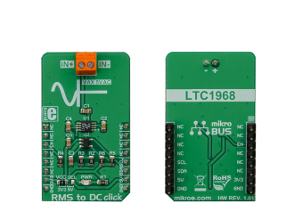
RMS to DC click is a Click board that is used to convert the RMS of the input signal into a DC voltage, with a value directly readable over the I2C interface. The Click board is equipped with the LTC1968, an RMS-to-DC converter IC, which outputs an analog voltage depending on the RMS value of the input signal.

No Abuse Reported

Do you want to subscribe in order to receive notifications regarding "RMS to DC click" changes.

Do you want to unsubscribe in order to stop receiving notifications regarding "RMS to DC click" changes.

Do you want to report abuse regarding "RMS to DC click".
  • mikroSDK Library 2.0.0.0
  • Comments (0)
DOWNLOAD LINK RELATED COMPILER CONTAINS
mikroBasic PRO for ARM
  • lib
  • src
  • exa
  • hlp
  • hex
  • sch
  • pcb
  • doc
mikroBasic PRO for AVR
  • lib
  • src
  • exa
  • hlp
  • hex
  • sch
  • pcb
  • doc
mikroBasic PRO for dsPIC30/33 & PIC24
  • lib
  • src
  • exa
  • hlp
  • hex
  • sch
  • pcb
  • doc
mikroBasic PRO for FT90x
  • lib
  • src
  • exa
  • hlp
  • hex
  • sch
  • pcb
  • doc
mikroBasic PRO for PIC
  • lib
  • src
  • exa
  • hlp
  • hex
  • sch
  • pcb
  • doc
mikroBasic PRO for PIC32
  • lib
  • src
  • exa
  • hlp
  • hex
  • sch
  • pcb
  • doc
mikroC PRO for ARM
  • lib
  • src
  • exa
  • hlp
  • hex
  • sch
  • pcb
  • doc
mikroC PRO for AVR
  • lib
  • src
  • exa
  • hlp
  • hex
  • sch
  • pcb
  • doc
mikroC PRO for dsPIC30/33 & PIC24
  • lib
  • src
  • exa
  • hlp
  • hex
  • sch
  • pcb
  • doc
mikroC PRO for FT90x
  • lib
  • src
  • exa
  • hlp
  • hex
  • sch
  • pcb
  • doc
mikroC PRO for PIC
  • lib
  • src
  • exa
  • hlp
  • hex
  • sch
  • pcb
  • doc
mikroC PRO for PIC32
  • lib
  • src
  • exa
  • hlp
  • hex
  • sch
  • pcb
  • doc
mikroPascal PRO for ARM
  • lib
  • src
  • exa
  • hlp
  • hex
  • sch
  • pcb
  • doc
mikroPascal PRO for AVR
  • lib
  • src
  • exa
  • hlp
  • hex
  • sch
  • pcb
  • doc
mikroPascal PRO for dsPIC30/33 & PIC24
  • lib
  • src
  • exa
  • hlp
  • hex
  • sch
  • pcb
  • doc
mikroPascal PRO for FT90x
  • lib
  • src
  • exa
  • hlp
  • hex
  • sch
  • pcb
  • doc
mikroPascal PRO for PIC
  • lib
  • src
  • exa
  • hlp
  • hex
  • sch
  • pcb
  • doc
mikroPascal PRO for PIC32
  • lib
  • src
  • exa
  • hlp
  • hex
  • sch
  • pcb
  • doc

mikroSDK Library Blog

RMS to DC click

RMS to DC click

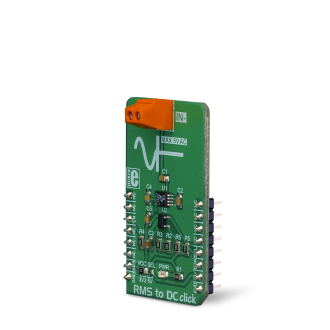
Native view of the RMS to DC Click board.

View full image
RMS to DC click

RMS to DC click

Front and back view of the RMS to DC Click board.

View full image

Library Description

The library performs an RMS to DC signal converting with 12bit resolution. It is also possible to get the averaged output DC signal (voltage), with a minimalized noise. For more details check the documentation.

Key functions:

  • uint16_t rms2dc_readADC( void ) - The function returns a 12bit result of AD conversion.
  • T_RMS2DC_V rms2dc_voutADC( T_RMS2DC_V vccSel ) - The function returns the output voltage value calculated to mV, depending on the power voltage selection.
  • T_RMS2DC_V rms2dc_avrgVoutADC( T_RMS2DC_V vccSelect, uint8_t nSamples ) - The function returns the averaged output voltage value calculated to mV, depending on the power voltage selection.

Examples description

The application is composed of the three sections :

  • System Initialization - Initializes peripherals and pins.
  • Application Initialization - Initializes I2C interface and turns ON the device.
  • Application Task - (code snippet) - Reads averaged DC output voltage calculated to mV, and sends results to the serial plotter. Note: The input voltage frequency should be in the range from 50Hz to 250kHz. Als,o the input voltage amplitude must be lower than 5V. In these conditions, the device can convert the RMS signal, in every form, to DC signal.
void applicationTask()
{
    outVoltDC = rms2dc_avrgVoutADC( _RMS2DC_VCC_3V3, 25 );
    
    plotData( outVoltDC );

    Delay_ms( 5 );
}

Additional Functions :

  • void plotData( T_RMS2DC_V plotY ) - Sends data (DC voltage) to the serial plotter.
  • void logData() - Sends DC voltage value to the uart terminal.


Other mikroE Libraries used in the example:

  • Conversions
  • I2C Library
  • UART Library

Additional notes and information

Depending on the development board you are using, you may need USB UART click, USB UART 2 click or RS232 click to connect to your PC, for development systems with no UART to USB interface available on the board. The terminal available in all MikroElektronika compilers, or any other terminal application of your choice, can be used to read the message.

ALSO FROM THIS AUTHOR

MikroPlot Data Visualization Tool

5

MikroPlot is a graph generator. It’s a simple tool to help you visualize sensor data recorded over time. It’s suitable for bio signals (ECG, EEG, EMG) as well as environmental data logging (temperature, humidity etc). The app can receive data sets directly from a microcontroller through a UART-USB connection.

[Learn More]

DSP click

0

DSP Click is a compact add-on board that contains a multi-effects digital signal processor. This board features the V1000, a complete multi-effects audio DSP with ultra-high quality audio performance in a rapid ‘time-to-market’ solution from Coolaudio. The V1000 includes its integrated RAM with 16 built-in multi-effects and reverb controlled via I/O pins or I2C interface. Combined with a low-cost A/D-D/A codec like the V4220, this Click board™ provides an ultra-low cost FX solution. This Click board™ is suitable for applications as a standalone audio player, PC accessories, and Hi-Tech toys, conventional consumer electronic devices, and many more.

[Learn More]

DC Motor 8 click

0

DC Motor 8 click is a DC motor driver. It can drive simple DC motors with brushes, providing them with a significant amount of current and voltage up to 40V. The click has one control input, that uses the PWM signal from the host MCU. It uses the half-bridge topology to regulate the speed of the motor rotation, employs advanced dead-time circuitry that monitors the output stage, providing maximum switching efficiency and features an advanced technique to avoid shoot-through currents.

[Learn More]