TOP Contributors

  1. MIKROE (2784 codes)
  2. Alcides Ramos (403 codes)
  3. Shawon Shahryiar (307 codes)
  4. jm_palomino (132 codes)
  5. Bugz Bensce (97 codes)
  6. S P (73 codes)
  7. dany (71 codes)
  8. MikroBUS.NET Team (35 codes)
  9. NART SCHINACKOW (34 codes)
  10. Armstrong Subero (27 codes)

Most Downloaded

  1. Timer Calculator (140969 times)
  2. FAT32 Library (73517 times)
  3. Network Ethernet Library (58322 times)
  4. USB Device Library (48510 times)
  5. Network WiFi Library (44134 times)
  6. FT800 Library (43689 times)
  7. GSM click (30547 times)
  8. mikroSDK (29295 times)
  9. PID Library (27220 times)
  10. microSD click (26931 times)
Libstock prefers package manager

Package Manager

We strongly encourage users to use Package manager for sharing their code on Libstock website, because it boosts your efficiency and leaves the end user with no room for error. [more info]

< Back
mikroSDK Library

Proximity 7 click

Rating:

5

Author: MIKROE

Last Updated: 2019-03-28

Package Version: 1.0.0.0

mikroSDK Library: 1.0.0.0

Category: Optical

Downloaded: 4279 times

Not followed.

License: MIT license  

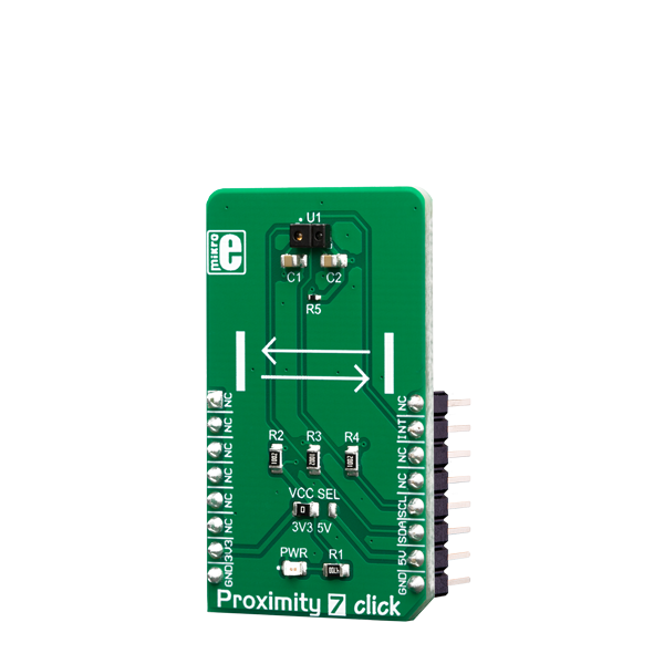
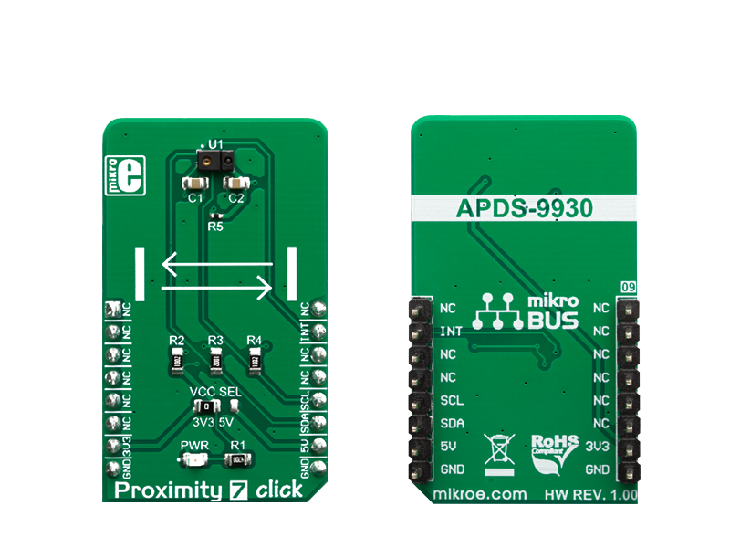
Proximity 7 Click is an advanced proximity and ambient light sensing Click board. It features the ADPS9930, a digital sensor IC equipped with two photodiodes (PD) and an IR LED, driven by a proprietary LED driver circuit.

No Abuse Reported

Do you want to subscribe in order to receive notifications regarding "Proximity 7 click" changes.

Do you want to unsubscribe in order to stop receiving notifications regarding "Proximity 7 click" changes.

Do you want to report abuse regarding "Proximity 7 click".

  • mikroSDK Library 2.0.0.0
  • Comments (0)
DOWNLOAD LINK RELATED COMPILER CONTAINS
mikroBasic PRO for ARM
  • lib
  • src
  • exa
  • hlp
  • hex
  • sch
  • pcb
  • doc
mikroBasic PRO for AVR
  • lib
  • src
  • exa
  • hlp
  • hex
  • sch
  • pcb
  • doc
mikroBasic PRO for dsPIC30/33 & PIC24
  • lib
  • src
  • exa
  • hlp
  • hex
  • sch
  • pcb
  • doc
mikroBasic PRO for FT90x
  • lib
  • src
  • exa
  • hlp
  • hex
  • sch
  • pcb
  • doc
mikroBasic PRO for PIC
  • lib
  • src
  • exa
  • hlp
  • hex
  • sch
  • pcb
  • doc
mikroBasic PRO for PIC32
  • lib
  • src
  • exa
  • hlp
  • hex
  • sch
  • pcb
  • doc
mikroC PRO for ARM
  • lib
  • src
  • exa
  • hlp
  • hex
  • sch
  • pcb
  • doc
mikroC PRO for AVR
  • lib
  • src
  • exa
  • hlp
  • hex
  • sch
  • pcb
  • doc
mikroC PRO for dsPIC30/33 & PIC24
  • lib
  • src
  • exa
  • hlp
  • hex
  • sch
  • pcb
  • doc
mikroC PRO for FT90x
  • lib
  • src
  • exa
  • hlp
  • hex
  • sch
  • pcb
  • doc
mikroC PRO for PIC
  • lib
  • src
  • exa
  • hlp
  • hex
  • sch
  • pcb
  • doc
mikroC PRO for PIC32
  • lib
  • src
  • exa
  • hlp
  • hex
  • sch
  • pcb
  • doc
mikroPascal PRO for ARM
  • lib
  • src
  • exa
  • hlp
  • hex
  • sch
  • pcb
  • doc
mikroPascal PRO for AVR
  • lib
  • src
  • exa
  • hlp
  • hex
  • sch
  • pcb
  • doc
mikroPascal PRO for dsPIC30/33 & PIC24
  • lib
  • src
  • exa
  • hlp
  • hex
  • sch
  • pcb
  • doc
mikroPascal PRO for FT90x
  • lib
  • src
  • exa
  • hlp
  • hex
  • sch
  • pcb
  • doc
mikroPascal PRO for PIC
  • lib
  • src
  • exa
  • hlp
  • hex
  • sch
  • pcb
  • doc
mikroPascal PRO for PIC32
  • lib
  • src
  • exa
  • hlp
  • hex
  • sch
  • pcb
  • doc

mikroSDK Library Blog

Proximity 7 click

Proximity 7 click

Native view of the Proximity 7 click board.

View full image
Proximity 7 click

Proximity 7 click

Front and back view of the Proximity 7 click board.

View full image

Library Description

Library contains functions for setting and getting register content Library contains functions for setting proximity and als integraton times as well as wait time Library contains functions for setting proximity and als channel 0 low and high thresholds Library contains functions for setting proximity and asl interrupt persistances Library contains functions for setting proximity pulse count and proximity offset Library contains function for setting constants for Lux calculation Library contains functions for getting Lux level and Int pin status Library contains functions for getting Als data from channels 0 and 1 Library contains function for getting proximity data.

Key functions:

  • void proximity7_setRegister( uint8_t *writeBuffer_, uint8_t nRegisters_ ) - sets register(s) content.
  • float proximity7_getLuxLevel( void ) - calculates LUX level based on Ch0 and Ch1 data and constants set by setConstants(); - function.
  • void proximity7_setConstants( float glassAttenuation, float constantB, float constantC, float constantD, float deviceFactor ) - sets constants for LUX calculation.

Examples description

The application is composed of the three sections :

  • System Initialization - Initializes I2C and LOG and sets INT pin as INPUT.
  • Application Initialization - Initializes I2C driver and writes basic settings to device registers.
  • Application Task - Logs lux level and proximity data.

Note:

  • When setting LED drive strength please note that if "proximity drive level - PDL" bit in "configuration register" is set to 1, LED drive current values are reduced by 9.
  • When setting wait time note that if "wait long - WLONG" bit is set to 1, time is 12x longer. Therefore if WLONG == 1 set time between 33ms and 8386.56ms.
  • When setting ALS gain note that if "ALS gain level - AGL" bit is set to 1, ALS gains are scaled by 0.16, otherwise, they are scaled by 1.
void applicationTask( )
{
    proximity7_getRegister( &readBuffer[0], _PROXIMITY7_STATUS, _PROXIMITY7_REPEATED_BYTE, 1 );
    
    alsValid = readBuffer[0] & _PROXIMITY7_ALS_VALID_MASK;
    proximityValid = readBuffer[0] & _PROXIMITY7_PROXIMITY_VALID_MASK;
    
    if (alsValid != 0 && proximityValid != 0)
    {
        mikrobus_logWrite( " ", _LOG_LINE );

        luxLevel = proximity7_getLuxLevel( );
        FloatToStr( luxLevel, text );
        mikrobus_logWrite( "> > > Lux level   : ", _LOG_TEXT );
        mikrobus_logWrite( text, _LOG_TEXT );
        mikrobus_logWrite( " lx", _LOG_LINE );

        proximity = proximity7_getProximityData( );
        FloatToStr( proximity, text );
        mikrobus_logWrite( "> > > Proximity   : ", _LOG_TEXT );
        mikrobus_logWrite( text, _LOG_TEXT );

        writeBuffer[0] = _PROXIMITY7_SPECIAL_FUNCTION | _PROXIMITY7_PROXIMITY_AND_ALS_INT_CLEAR;
        proximity7_setRegister( &writeBuffer[0], 1 );
    }
    
    Delay_ms(300);
}

Other mikroE Libraries used in the example:

  • I2C
  • UART
  • Conversions

Additional notes and informations

Depending on the development board you are using, you may need USB UART clickUSB UART 2 click or RS232 click to connect to your PC, for development systems with no UART to USB interface available on the board. The terminal available in all MikroElektronika compilers, or any other terminal application of your choice, can be used to read the message.

ALSO FROM THIS AUTHOR

Joystick 3 Click

0

Joystick 3 Click is a compact add-on board that can fulfill your directional analog input needs. This board features 2765, a high-quality mini 2-axis analog output thumbstick from Adafruit Industries. This small joystick is a 'self-centering' analog-type with a black rocker cap similar to the PSP joysticks. It comprises two 10kΩ potentiometers, one for up/down and another for left/right direction. Knowing that this joystick represents an analog type, it connects with mikroBUS™ through the SPI interface through the MCP3204 12-bit A/D converter.

[Learn More]

Balancer 5 Click

0

Balancer 5 Click is an intelligent 2-cell Li-Ion battery charger, system power manager, and a battery fuel gauge Click board™. Balancer 5 Click is based on BQ25887 controller which has some extra features enabling charging without too much hassle.

[Learn More]

Brushless 21 Click

0

Brushless 21 Click is a compact add-on board suitable for controlling brushless DC (BLDC) motors with any MCU. This board features the AMT49400, an advanced 3-phase, sensorless BLDC motor driver with integrated power MOSFETs from Allegro Microsystems. The AMT49400 is rated for an operating voltage range from 4V to 16V. Motor rotation speed is controlled by applying a duty cycle command to the PWM input, while a simple I2C interface is provided for setting motor-rated voltage, rated current, rated speed, resistance, and startup profiles.

[Learn More]