TOP Contributors

  1. MIKROE (2784 codes)
  2. Alcides Ramos (405 codes)
  3. Shawon Shahryiar (307 codes)
  4. jm_palomino (133 codes)
  5. Bugz Bensce (97 codes)
  6. S P (73 codes)
  7. dany (71 codes)
  8. MikroBUS.NET Team (35 codes)
  9. NART SCHINACKOW (34 codes)
  10. Armstrong Subero (27 codes)

Most Downloaded

  1. Timer Calculator (141228 times)
  2. FAT32 Library (74037 times)
  3. Network Ethernet Library (58659 times)
  4. USB Device Library (48766 times)
  5. Network WiFi Library (44485 times)
  6. FT800 Library (44034 times)
  7. GSM click (30784 times)
  8. mikroSDK (29602 times)
  9. PID Library (27342 times)
  10. microSD click (27188 times)
Libstock prefers package manager

Package Manager

We strongly encourage users to use Package manager for sharing their code on Libstock website, because it boosts your efficiency and leaves the end user with no room for error. [more info]

< Back
mikroSDK Library

Waveform 2 click

Rating:

6

Author: MIKROE

Last Updated: 2021-08-13

Package Version: 1.0.0.0

mikroSDK Library: 1.0.0.0

Category: Clock generator

Downloaded: 3425 times

Not followed.

License: MIT license  

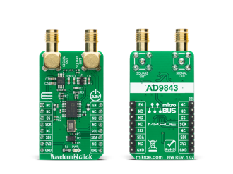
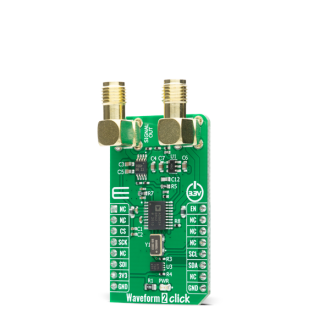
Waveform 2 Click is a compact add-on board that contains a direct digital synthesis device for waveform generator applications. This board features the AD9834, a 75 MHz low power DDS device capable of producing high-performance sine/triangle/square outputs from Analog Devices.

No Abuse Reported

Do you want to subscribe in order to receive notifications regarding "Waveform 2 click" changes.

Do you want to unsubscribe in order to stop receiving notifications regarding "Waveform 2 click" changes.

Do you want to report abuse regarding "Waveform 2 click".
  • mikroSDK Library 2.0.0.0
  • Comments (1)
DOWNLOAD LINK RELATED COMPILER CONTAINS
mikroBasic PRO for ARM
  • lib
  • src
  • exa
  • hlp
  • hex
  • sch
  • pcb
  • doc
mikroBasic PRO for AVR
  • lib
  • src
  • exa
  • hlp
  • hex
  • sch
  • pcb
  • doc
mikroBasic PRO for dsPIC30/33 & PIC24
  • lib
  • src
  • exa
  • hlp
  • hex
  • sch
  • pcb
  • doc
mikroBasic PRO for FT90x
  • lib
  • src
  • exa
  • hlp
  • hex
  • sch
  • pcb
  • doc
mikroBasic PRO for PIC
  • lib
  • src
  • exa
  • hlp
  • hex
  • sch
  • pcb
  • doc
mikroBasic PRO for PIC32
  • lib
  • src
  • exa
  • hlp
  • hex
  • sch
  • pcb
  • doc
mikroC PRO for ARM
  • lib
  • src
  • exa
  • hlp
  • hex
  • sch
  • pcb
  • doc
mikroC PRO for AVR
  • lib
  • src
  • exa
  • hlp
  • hex
  • sch
  • pcb
  • doc
mikroC PRO for dsPIC30/33 & PIC24
  • lib
  • src
  • exa
  • hlp
  • hex
  • sch
  • pcb
  • doc
mikroC PRO for FT90x
  • lib
  • src
  • exa
  • hlp
  • hex
  • sch
  • pcb
  • doc
mikroC PRO for PIC
  • lib
  • src
  • exa
  • hlp
  • hex
  • sch
  • pcb
  • doc
mikroC PRO for PIC32
  • lib
  • src
  • exa
  • hlp
  • hex
  • sch
  • pcb
  • doc
mikroPascal PRO for ARM
  • lib
  • src
  • exa
  • hlp
  • hex
  • sch
  • pcb
  • doc
mikroPascal PRO for AVR
  • lib
  • src
  • exa
  • hlp
  • hex
  • sch
  • pcb
  • doc
mikroPascal PRO for dsPIC30/33 & PIC24
  • lib
  • src
  • exa
  • hlp
  • hex
  • sch
  • pcb
  • doc
mikroPascal PRO for FT90x
  • lib
  • src
  • exa
  • hlp
  • hex
  • sch
  • pcb
  • doc
mikroPascal PRO for PIC
  • lib
  • src
  • exa
  • hlp
  • hex
  • sch
  • pcb
  • doc
mikroPascal PRO for PIC32
  • lib
  • src
  • exa
  • hlp
  • hex
  • sch
  • pcb
  • doc

mikroSDK Library Blog

Waveform 2 Click

Waveform 2 Click

Native view of the Waveform 2 Click board.

View full image
Waveform 2 Click

Waveform 2 Click

Front and back view of the Waveform 2 Click board.

View full image

Library Description

Library contains generic functions for working with the Waveform 2 Click™ board.

Key functions:

  • void waveform2_set_freq ( uint32_t freq ) - Function for setting the output frequency.
  • void waveform2_sine_output ( void ) - Function for setting the sine output.
  • void waveform2_triangle_output ( void ) - Function for setting the triangle output.

Examples description

The application is composed of three sections :

  • System Initialization - Initialize the GPIO and communication structures.
  • Application Initialization - Initialize the communication interface and configure the Click board™.
  • Application Task - Predefined characters are inputed from the serial port. Depending on the character sent the signal frequency, waveform or amplitude will be changed.
  • Command: [ + ] - Increase frequency [ - ] - Decrease frequency [ t ] - Triangle-shaped signal [ s ] - The signal in the form of a sinusoid
void application_task ( )
{
    char rx_data;
    uint32_t freq_data;

    if ( UART_Rdy_Ptr( ) )
    {
       rx_data = UART_Rd_Ptr( );
    }

    if ( rx_data > 0 )
    {
        switch ( rx_data )
        {
            case '+': 
            {
                f += 10;
                freq_data = f << 14;
                waveform2_set_freq( freq_data );
                rx_data = 0;
                mikrobus_logWrite( ">> Increasing the frequency ", _LOG_LINE );
                break;
            }

            case '-': 
            {
                if ( f <= 9 )
                { 
                    f = 0;
                }
                f -= 10;
                freq_data = f << 14;
                waveform2_set_freq( freq_data );
                rx_data = 0;
                mikrobus_logWrite( ">> Decreasing the frequency ", _LOG_LINE );
                break;
            }

            case 't': 
            {
                waveform2_triangle_output( );
                rx_data = 0;
                mikrobus_logWrite( ">> Triangle output ", _LOG_LINE );
                break;
            }

            case 's': 
            {
                waveform2_sine_output( );
                rx_data = 0;
                mikrobus_logWrite( ">> Sinusoid output ", _LOG_LINE );
                break;
            }
        }
    }
    rx_data = 0;
}


Additional Functions : aprox_freq_calculation( ) - This function is used to calculate the aproximate value that will be written to the frequency set register.

Other mikroE Libraries used in the example:

  • UART Library
  • I2C Library
  • SPI Library
  • Conversions Library

Additional notes and informations

Depending on the development board you are using, you may need USB UART clickUSB UART 2 click or RS232 click to connect to your PC, for development systems with no UART to USB interface available on the board. The terminal available in all MikroElektronika compilers, or any other terminal application of your choice, can be used to read the message.

ALSO FROM THIS AUTHOR

GNSS MAX Click

0

GNSS MAX Click is a compact add-on board that provides fast positioning capability. This board features the MAX-M10S, an ultra-low-power GNSS receiver for high-performance asset-tracking from u-blox. The MAX-M10S supports the concurrent reception of four GNSS (GPS, GLONASS, Galileo, and BeiDou), which maximizes the position availability, particularly under challenging conditions such as in deep urban canyons. It is built on the u-blox M10 GNSS platform, which provides exceptional sensitivity and acquisition times for all L1 GNSS systems. It also comes with a configurable host interface, and advanced jamming and spoofing detection.

[Learn More]

RadioStation Click

0

RadioStation Click is a unique Click board™ that can be used to broadcast the music via the FM radio band. It features the Si4713-B30 from Silicon Labs, the best in class integrated FM broadcast stereo transmitter, which operates in the frequency range of 76MHz to 108MHz. It can also broadcast RDS/RDBS data. The Click board™ can be equipped with a small FM antenna, which is used to extend the broadcasting range.

[Learn More]

Accel 29 Click

0

Accel 29 Click is a compact add-on board that contains an acceleration sensor. This board features the ADXL314, a three-axis ±200g accelerometer from Analog Devices. The ADXL314 offers 16-bit digital output data with a configurable host interface that supports SPI and I2C serial communication. An integrated memory management system with a 32-level FIFO buffer can store data to minimize host processor activity and lower overall system power consumption. Low power modes enable intelligent motion-based power management with threshold sensing and active acceleration measurement at low power dissipation.

[Learn More]