TOP Contributors

  1. MIKROE (2784 codes)
  2. Alcides Ramos (392 codes)
  3. Shawon Shahryiar (307 codes)
  4. jm_palomino (123 codes)
  5. Bugz Bensce (97 codes)
  6. S P (73 codes)
  7. dany (71 codes)
  8. MikroBUS.NET Team (35 codes)
  9. NART SCHINACKOW (34 codes)
  10. Armstrong Subero (27 codes)

Most Downloaded

  1. Timer Calculator (140552 times)
  2. FAT32 Library (73048 times)
  3. Network Ethernet Library (58051 times)
  4. USB Device Library (48220 times)
  5. Network WiFi Library (43833 times)
  6. FT800 Library (43295 times)
  7. GSM click (30359 times)
  8. mikroSDK (28992 times)
  9. PID Library (27119 times)
  10. microSD click (26722 times)
Libstock prefers package manager

Package Manager

We strongly encourage users to use Package manager for sharing their code on Libstock website, because it boosts your efficiency and leaves the end user with no room for error. [more info]

< Back
mikroSDK Library

Buck 13 click

Rating:

5

Author: MIKROE

Last Updated: 2019-07-19

Package Version: 1.0.0.0

mikroSDK Library: 1.0.0.0

Category: Buck

Downloaded: 3578 times

Not followed.

License: MIT license  

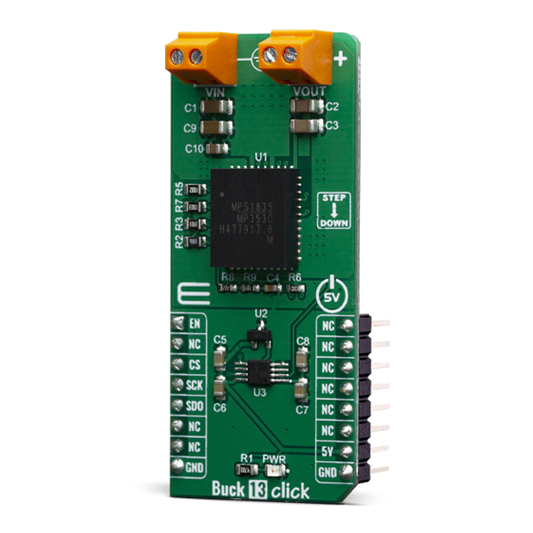
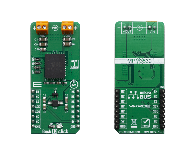
Buck 13 Click is a high-efficiency step-down converter which provides a highly regulated output voltage derived from the connected power source, rated from 4.5V to 5.5V.

No Abuse Reported

Do you want to subscribe in order to receive notifications regarding "Buck 13 click" changes.

Do you want to unsubscribe in order to stop receiving notifications regarding "Buck 13 click" changes.

Do you want to report abuse regarding "Buck 13 click".

  • mikroSDK Library 2.0.0.0
  • Comments (0)
DOWNLOAD LINK RELATED COMPILER CONTAINS
mikroBasic PRO for ARM
  • lib
  • src
  • exa
  • hlp
  • hex
  • sch
  • pcb
  • doc
mikroBasic PRO for AVR
  • lib
  • src
  • exa
  • hlp
  • hex
  • sch
  • pcb
  • doc
mikroBasic PRO for dsPIC30/33 & PIC24
  • lib
  • src
  • exa
  • hlp
  • hex
  • sch
  • pcb
  • doc
mikroBasic PRO for FT90x
  • lib
  • src
  • exa
  • hlp
  • hex
  • sch
  • pcb
  • doc
mikroBasic PRO for PIC
  • lib
  • src
  • exa
  • hlp
  • hex
  • sch
  • pcb
  • doc
mikroBasic PRO for PIC32
  • lib
  • src
  • exa
  • hlp
  • hex
  • sch
  • pcb
  • doc
mikroC PRO for ARM
  • lib
  • src
  • exa
  • hlp
  • hex
  • sch
  • pcb
  • doc
mikroC PRO for AVR
  • lib
  • src
  • exa
  • hlp
  • hex
  • sch
  • pcb
  • doc
mikroC PRO for dsPIC30/33 & PIC24
  • lib
  • src
  • exa
  • hlp
  • hex
  • sch
  • pcb
  • doc
mikroC PRO for FT90x
  • lib
  • src
  • exa
  • hlp
  • hex
  • sch
  • pcb
  • doc
mikroC PRO for PIC
  • lib
  • src
  • exa
  • hlp
  • hex
  • sch
  • pcb
  • doc
mikroC PRO for PIC32
  • lib
  • src
  • exa
  • hlp
  • hex
  • sch
  • pcb
  • doc
mikroPascal PRO for ARM
  • lib
  • src
  • exa
  • hlp
  • hex
  • sch
  • pcb
  • doc
mikroPascal PRO for AVR
  • lib
  • src
  • exa
  • hlp
  • hex
  • sch
  • pcb
  • doc
mikroPascal PRO for dsPIC30/33 & PIC24
  • lib
  • src
  • exa
  • hlp
  • hex
  • sch
  • pcb
  • doc
mikroPascal PRO for FT90x
  • lib
  • src
  • exa
  • hlp
  • hex
  • sch
  • pcb
  • doc
mikroPascal PRO for PIC
  • lib
  • src
  • exa
  • hlp
  • hex
  • sch
  • pcb
  • doc
mikroPascal PRO for PIC32
  • lib
  • src
  • exa
  • hlp
  • hex
  • sch
  • pcb
  • doc

mikroSDK Library Blog

Buck 13 click

Buck 13 click

Native view of the Buck 13 click board.

View full image
Buck 13 click

Buck 13 click

Front and back view of the Buck 13 click board.

View full image

Library Description

This library performs a control of the Buck 13 click board, which is used to convert the input DC voltage, in the range from 6.5V to 50V, to output DC voltage of 3.3V, with maximal current of 3A. Library uses SPI serial interface to allow the ADC output reading from the Buck 13. For more details check documentation.

Key functions:

  • void buck13_spiDriverInit( T_BUCK13_P gpioObj, T_BUCK13_P spiObj ) - This function initializes SPI serial interface.
  • void buck13_enable( T_BUCK13_STATE pwr_state ) - This function allows user to perform a control of the Buck 13 output.
  • uint16_t buck13_getVoltage( void ) - This function returns the output voltage value calculated to millivolts.

Examples description

The application is composed of three sections :

  • System Initialization - Initializes peripherals and pins.
  • Application Initialization - Initializes SPI serial interface and turns OFF the Buck 13 output as default state. Also writes possible commands to the uart terminal.
  • Application Task - (code snippet) - Checks the command entered by user and executes the operation determined by selected command. If entered command was invalid sends a report to the uart terminal. Also the report will be sent to the uart terminal after each entered command and executed operation. Note: Input voltage range is from 6.5V to 50V Output voltage is about 3.3V Current limit is 3A.
void applicationTask()
{
    rx_dat = UART_Rdy_Ptr();
    
    if (rx_dat != 0)
    {
        rx_dat = UART_Rd_Ptr();
        
        switch (rx_dat)
        {
            case 'e' :
            {
                if (out_state == _BUCK13_DISABLE)
                {
                    buck13_enable( _BUCK13_ENABLE );
                    out_state = _BUCK13_ENABLE;
                    mikrobus_logWrite( "** Buck 13 output is enabled now.", _LOG_LINE );
                }
                else
                {
                    mikrobus_logWrite( "** Buck 13 output is already enabled.", _LOG_LINE );
                }
            break;
            }
            case 'd' :
            {
                if (out_state == _BUCK13_ENABLE)
                {
                    buck13_enable( _BUCK13_DISABLE );
                    out_state = _BUCK13_DISABLE;
                    mikrobus_logWrite( "** Buck 13 output is disabled now.", _LOG_LINE );
                }
                else
                {
                    mikrobus_logWrite( "** Buck 13 output is already disabled.", _LOG_LINE );
                }
            break;
            }
            case 'v' :
            {
                out_voltage = buck13_getVoltage();
                
                WordToStr( out_voltage, text );
                Ltrim( text );
                mikrobus_logWrite( "** VOUT = ", _LOG_TEXT );
                mikrobus_logWrite( text, _LOG_TEXT );
                mikrobus_logWrite( " mV.", _LOG_LINE );
            break;
            }
            case 'c' :
            {
                writeCmd();
            break;
            }
            default :
            {
                mikrobus_logWrite( "*****    Invalid command.    *****", _LOG_LINE );
                writeCmd();
            break;
            }
        }
    }
}


Additional Functions :

  • writeCmd - Writes possible commands for the user to the uart terminal.

Other mikroE Libraries used in the example:

  • Conversions
  • C_String
  • SPI
  • UART

Additional notes and informations

Depending on the development board you are using, you may need USB UART clickUSB UART 2 click or RS232 click to connect to your PC, for development systems with no UART to USB interface available on the board. The terminal available in all MikroElektronika compilers, or any other terminal application of your choice, can be used to read the message.

ALSO FROM THIS AUTHOR

Current 7 Click

0

Current 7 Click is a compact add-on board providing a precise and accurate current sensing solution. This board features the INA282, a wide common-mode range, bidirectional, high-accuracy current shunt monitor from Texas Instruments. The INA282 represents a voltage output current shunt monitor that can sense drops across shunts at common-mode voltages from –14 V to +80 V, independent of the supply voltage, which operates in a range from 2.7V up to 18V supply. The zero-drift topology enables high-precision measurements with maximum input offset voltages as low as 70μV. Also, the user is allowed to process the output signal in analog or digital form.

[Learn More]

LTE Cat.4 Click

0

LTE Cat.4 Click (for Europe) is a compact add-on board made specially for 4G M2M and IoT applications in Europe. This board features the EG95EXGA-128-SGNS, an IoT/M2M-optimized LTE Cat.4 module that meets the 3GPP Release 11 standard from Quectel. It supports multiple wireless standards, including LTE-FDD, WCDMA, and GSM, ensuring broad network compatibility. Key features include multi-band LTE support (B1/B3/B7/B8/B20/B28), RX diversity for bands B1 and B8, and multi-constellation GNSS (GPS, GLONASS, BeiDou/Compass, Galileo, QZSS). It also integrates a 16-bit mono audio codec for voice functionality with support for CTIA standard headphones. Additionally, it offers a USB Type C connector for power and data transfer, AT command communication, and firmware upgrades.

[Learn More]

Microwave 6 Click

0

Microwave 6 Click is a compact add-on board that utilizes the Doppler Shift Phenomenon to sense motion. This board features the PD-V8-S, a high-frequency microwave sensor from Ningbo Pdlux Electronic Technology. The transmitter on this transceiver works on a 5.8GHz frequency over the patch antenna, with a 2-3kHz pulse repetition frequency. The strength of the sensor’s output, in other words, the detection range, depends on the Signal-to-Noise ratio.

[Learn More]