TOP Contributors

  1. MIKROE (2784 codes)
  2. Alcides Ramos (405 codes)
  3. Shawon Shahryiar (307 codes)
  4. jm_palomino (133 codes)
  5. Bugz Bensce (97 codes)
  6. S P (73 codes)
  7. dany (71 codes)
  8. MikroBUS.NET Team (35 codes)
  9. NART SCHINACKOW (34 codes)
  10. Armstrong Subero (27 codes)

Most Downloaded

  1. Timer Calculator (141582 times)
  2. FAT32 Library (74522 times)
  3. Network Ethernet Library (59057 times)
  4. USB Device Library (49065 times)
  5. Network WiFi Library (44834 times)
  6. FT800 Library (44388 times)
  7. GSM click (31067 times)
  8. mikroSDK (29928 times)
  9. microSD click (27501 times)
  10. PID Library (27491 times)
Libstock prefers package manager

Package Manager

We strongly encourage users to use Package manager for sharing their code on Libstock website, because it boosts your efficiency and leaves the end user with no room for error. [more info]

< Back
mikroSDK Library

Thermo 13 click

Rating:

5

Author: MIKROE

Last Updated: 2019-08-08

Package Version: 1.0.0.0

mikroSDK Library: 1.0.0.0

Category: Temperature & humidity

Downloaded: 4884 times

Not followed.

License: MIT license  

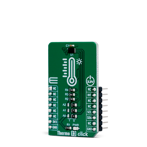
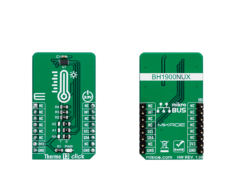
Thermo 13 Click is a Click board equipped with the sensor IC, which can digitize temperature measurements between -30°C and +95°C so that the temperature measurement data can be processed by the host MCU.

No Abuse Reported

Do you want to subscribe in order to receive notifications regarding "Thermo 13 click" changes.

Do you want to unsubscribe in order to stop receiving notifications regarding "Thermo 13 click" changes.

Do you want to report abuse regarding "Thermo 13 click".

  • mikroSDK Library 2.0.0.0
  • Comments (0)
DOWNLOAD LINK RELATED COMPILER CONTAINS
mikroBasic PRO for ARM
  • lib
  • src
  • exa
  • hlp
  • hex
  • sch
  • pcb
  • doc
mikroBasic PRO for AVR
  • lib
  • src
  • exa
  • hlp
  • hex
  • sch
  • pcb
  • doc
mikroBasic PRO for dsPIC30/33 & PIC24
  • lib
  • src
  • exa
  • hlp
  • hex
  • sch
  • pcb
  • doc
mikroBasic PRO for FT90x
  • lib
  • src
  • exa
  • hlp
  • hex
  • sch
  • pcb
  • doc
mikroBasic PRO for PIC
  • lib
  • src
  • exa
  • hlp
  • hex
  • sch
  • pcb
  • doc
mikroBasic PRO for PIC32
  • lib
  • src
  • exa
  • hlp
  • hex
  • sch
  • pcb
  • doc
mikroC PRO for ARM
  • lib
  • src
  • exa
  • hlp
  • hex
  • sch
  • pcb
  • doc
mikroC PRO for AVR
  • lib
  • src
  • exa
  • hlp
  • hex
  • sch
  • pcb
  • doc
mikroC PRO for dsPIC30/33 & PIC24
  • lib
  • src
  • exa
  • hlp
  • hex
  • sch
  • pcb
  • doc
mikroC PRO for FT90x
  • lib
  • src
  • exa
  • hlp
  • hex
  • sch
  • pcb
  • doc
mikroC PRO for PIC
  • lib
  • src
  • exa
  • hlp
  • hex
  • sch
  • pcb
  • doc
mikroC PRO for PIC32
  • lib
  • src
  • exa
  • hlp
  • hex
  • sch
  • pcb
  • doc
mikroPascal PRO for ARM
  • lib
  • src
  • exa
  • hlp
  • hex
  • sch
  • pcb
  • doc
mikroPascal PRO for AVR
  • lib
  • src
  • exa
  • hlp
  • hex
  • sch
  • pcb
  • doc
mikroPascal PRO for dsPIC30/33 & PIC24
  • lib
  • src
  • exa
  • hlp
  • hex
  • sch
  • pcb
  • doc
mikroPascal PRO for FT90x
  • lib
  • src
  • exa
  • hlp
  • hex
  • sch
  • pcb
  • doc
mikroPascal PRO for PIC
  • lib
  • src
  • exa
  • hlp
  • hex
  • sch
  • pcb
  • doc
mikroPascal PRO for PIC32
  • lib
  • src
  • exa
  • hlp
  • hex
  • sch
  • pcb
  • doc

mikroSDK Library Blog

Thermo 13 click

Thermo 13 click

Native view of the Thermo 13 Click board.

View full image
Thermo 13 click

Thermo 13 click

Front and back view of the Thermo 13 Click board.

View full image

Library Description

The library initializes and defines the I2C bus driver and drivers that offer a choice for read data form register. The library includes function for read Temperature data and function for read and set temperature limit low/high register. The user also has the function for configuration chip and read Interrupt (INT pin) state.

Key functions:

  • float thermo13_getAmbientTemperatureData(uint8_t tempIn) - Ambient temperature data
  • void thermo13_setTempLimit(uint8_t tempReg, float temp) - Set temperature limit register
  • void thermo13_configuration(uint8_t cfgData) - Configuration register

Examples description

  • System Initialization - Initializes I2C module and sets INT pin as INPUT
  • Application Initialization - Initializes the driver init, configures the module and reads the temperature Limit LOW/HIGH values that are set
  • Application Task - Reads ambient temperature data and this data logs to USBUART every 1500ms
void applicationTask()
{
    float Temperature;

    Temperature = thermo13_getAmbientTemperatureData( _THERMO13_TEMP_IN_CELSIUS );
    FloatToStr(Temperature, demoText);
    mikrobus_logWrite("** Temperature : ", _LOG_TEXT);
    mikrobus_logWrite(demoText, _LOG_LINE);

    mikrobus_logWrite( " ---------------------------- ", _LOG_LINE);

    Delay_ms( 1500 );
}

Other mikroE Libraries used in the example:

  • I2C Library
  • UART Library
  • Conversions Library

Additional notes and informations

Depending on the development board you are using, you may need USB UART click, USB UART 2 click or RS232 click to connect to your PC, for development systems with no UART to USB interface available on the board. The terminal available in all MikroElektronika compilers, or any other terminal application of your choice, can be used to read the message.

ALSO FROM THIS AUTHOR

ADC 9 click

5

ADC 9 Click is based on MCP3564 a 24-bit Delta-Sigma Analog-to-Digital Converter with programmable data rate of up to 153.6 ksps from Microchip. It offer integrated features, such as internal oscillator, temperature sensor and burnout sensor detection, in order to reduce system component count and total solution cost.

[Learn More]

Shake2Wake Click

0

Shake2Wake Click carries an ADXL362 ultralow power, 3-axis MEMS accelerometer and ADP195 load switch. The distinguishing feature of this IC is that it incorporates several activity detection modes.

[Learn More]

Button R Click

0

Button R Click is the simplest solution for adding a single pushbutton to your design. The button itself is transparent, 6.8mm in diameter and has a red LED backlight. When pressed, it sends an interrupt signal to the target board microcontroller. The backlight LED is controlled separately through the mikroBUS PWM pin, so you can program all kinds of patterns (varying level of light intensity or rate of blinking on subsequent button presses). The board can use either a 3.3V or a 5V power supply.

[Learn More]