TOP Contributors

  1. MIKROE (2784 codes)
  2. Alcides Ramos (405 codes)
  3. Shawon Shahryiar (307 codes)
  4. jm_palomino (133 codes)
  5. Bugz Bensce (97 codes)
  6. S P (73 codes)
  7. dany (71 codes)
  8. MikroBUS.NET Team (35 codes)
  9. NART SCHINACKOW (34 codes)
  10. Armstrong Subero (27 codes)

Most Downloaded

  1. Timer Calculator (141702 times)
  2. FAT32 Library (74778 times)
  3. Network Ethernet Library (59221 times)
  4. USB Device Library (49226 times)
  5. Network WiFi Library (44999 times)
  6. FT800 Library (44536 times)
  7. GSM click (31203 times)
  8. mikroSDK (30104 times)
  9. microSD click (27586 times)
  10. PID Library (27543 times)
Libstock prefers package manager

Package Manager

We strongly encourage users to use Package manager for sharing their code on Libstock website, because it boosts your efficiency and leaves the end user with no room for error. [more info]

< Back
mikroSDK Library

Button ALARM click

Rating:

5

Author: MIKROE

Last Updated: 2019-09-25

Package Version: 1.0.0.0

mikroSDK Library: 1.0.0.0

Category: Pushbutton/Switches

Downloaded: 3843 times

Not followed.

License: MIT license  

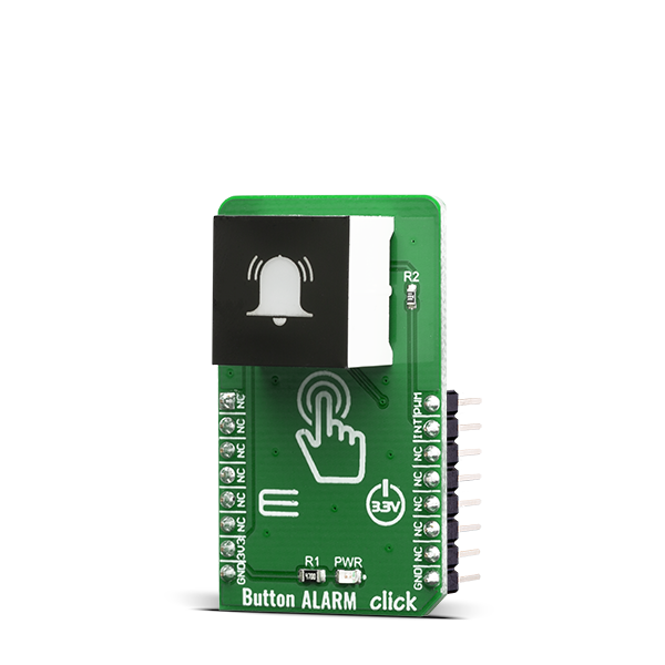
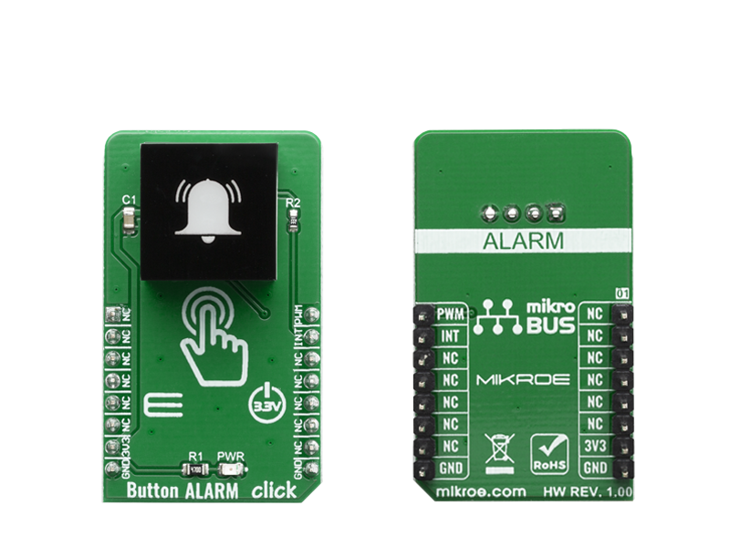
Button Alarm Click is a very interesting interactive gadget on a Click board. It is an integrated capacitive touch sensor display in the form of a button.

No Abuse Reported

Do you want to subscribe in order to receive notifications regarding "Button ALARM click" changes.

Do you want to unsubscribe in order to stop receiving notifications regarding "Button ALARM click" changes.

Do you want to report abuse regarding "Button ALARM click".

  • mikroSDK Library 2.0.0.0
  • Comments (0)
DOWNLOAD LINK RELATED COMPILER CONTAINS
mikroBasic PRO for ARM
  • lib
  • src
  • exa
  • hlp
  • hex
  • sch
  • pcb
  • doc
mikroBasic PRO for AVR
  • lib
  • src
  • exa
  • hlp
  • hex
  • sch
  • pcb
  • doc
mikroBasic PRO for dsPIC30/33 & PIC24
  • lib
  • src
  • exa
  • hlp
  • hex
  • sch
  • pcb
  • doc
mikroBasic PRO for FT90x
  • lib
  • src
  • exa
  • hlp
  • hex
  • sch
  • pcb
  • doc
mikroBasic PRO for PIC
  • lib
  • src
  • exa
  • hlp
  • hex
  • sch
  • pcb
  • doc
mikroBasic PRO for PIC32
  • lib
  • src
  • exa
  • hlp
  • hex
  • sch
  • pcb
  • doc
mikroC PRO for ARM
  • lib
  • src
  • exa
  • hlp
  • hex
  • sch
  • pcb
  • doc
mikroC PRO for AVR
  • lib
  • src
  • exa
  • hlp
  • hex
  • sch
  • pcb
  • doc
mikroC PRO for dsPIC30/33 & PIC24
  • lib
  • src
  • exa
  • hlp
  • hex
  • sch
  • pcb
  • doc
mikroC PRO for FT90x
  • lib
  • src
  • exa
  • hlp
  • hex
  • sch
  • pcb
  • doc
mikroC PRO for PIC
  • lib
  • src
  • exa
  • hlp
  • hex
  • sch
  • pcb
  • doc
mikroC PRO for PIC32
  • lib
  • src
  • exa
  • hlp
  • hex
  • sch
  • pcb
  • doc
mikroPascal PRO for ARM
  • lib
  • src
  • exa
  • hlp
  • hex
  • sch
  • pcb
  • doc
mikroPascal PRO for AVR
  • lib
  • src
  • exa
  • hlp
  • hex
  • sch
  • pcb
  • doc
mikroPascal PRO for dsPIC30/33 & PIC24
  • lib
  • src
  • exa
  • hlp
  • hex
  • sch
  • pcb
  • doc
mikroPascal PRO for FT90x
  • lib
  • src
  • exa
  • hlp
  • hex
  • sch
  • pcb
  • doc
mikroPascal PRO for PIC
  • lib
  • src
  • exa
  • hlp
  • hex
  • sch
  • pcb
  • doc
mikroPascal PRO for PIC32
  • lib
  • src
  • exa
  • hlp
  • hex
  • sch
  • pcb
  • doc

mikroSDK Library Blog

Button ALARM click

Button ALARM click

Native view of the Button ALARM click board.

View full image
Button ALARM click

Button ALARM click

Front and back view of the Button ALARM click board.

View full image

Library Description

The library covers all the necessary functions to control Button ALARM Click board. The library contains a function that checks and returns the state of the alarm button - whether it is pressed or not. Using the PWM function, you can adjust the LED light of the alarm button.

Key functions:

  • uint8_t buttonalarm_getButtonState() - Gets state of the alarm button function.

Examples description

The application is composed of the three sections :

  • System Initialization - Initializes GPIO and LOG structures, set INT pin as input and start to write log.
  • Application Initialization - Initialization driver enable's - GPIO, PWM initialization set PWM duty cycle and PWM frequency, start PWM, also to write log.
  • Application Task - This is an example which demonstrates the use of Button ALARM Click board. This example shows the automatic control of the alarm button. When we press and hold button, button stops blinking and start dimming. Results are being sent to the Usart Terminal where you can track their changes. All data logs on usb uart for approximately every 1 sec when the data value changes.
void applicationTask()
{
    buttonState = buttonalarm_getButtonState();
    
    cnt = 0;
    while ( ( cnt < 200 ) && ( buttonState == _BUTTONALARM_BUTTON_STATE_OFF ) )
    {
        buttonState = buttonalarm_getButtonState();
        buttonalarm_pwmSetDuty( _BUTTONALARM_DUTY_CYCLE_ON );
        cnt++;
        Delay_ms( 1 );
    }

    cnt = 0;
    while ( ( cnt < 200 ) && ( buttonState == _BUTTONALARM_BUTTON_STATE_OFF ) )
    {
        buttonState = buttonalarm_getButtonState();
        buttonalarm_pwmSetDuty( _BUTTONALARM_DUTY_CYCLE_OFF );
        cnt++;
        Delay_ms( 1 );
    }

    if( buttonState )
    {
        mikrobus_logWrite("  Button is pressed  ", _LOG_LINE);

        while ( dutyCycle < _BUTTONALARM_DUTY_CYCLE_ON )
        {
            dutyCycle += 200;
            buttonalarm_pwmSetDuty( dutyCycle );

            if ( dutyCycle > _BUTTONALARM_DUTY_CYCLE_ON )
            {
                dutyCycle = _BUTTONALARM_DUTY_CYCLE_OFF;
                buttonalarm_pwmSetDuty( dutyCycle );
                Delay_ms( 100 );
            }
            Delay_ms( 50 );
        }
        dutyCycle = _BUTTONALARM_DUTY_CYCLE_OFF;
        mikrobus_logWrite( "---------------------", _LOG_LINE );
    }
}

Additional Functions :

  • uint32_t buttonalarm_pwmInit( uint16_t freq ) -Initializes the Timer module in PWM mode.
  • void buttonalarm_pwmSetDuty( uint16_t duty ) -The function changes PWM duty ratio.
  • void buttonalarm_pwmStart() -Starts appropriate PWM module.
  • void buttonalarm_pwmStop() -Stops appropriate PWM module.

Other mikroE Libraries used in the example:

  • PWM
  • UART

Additional notes and informations

Depending on the development board you are using, you may need USB UART clickUSB UART 2 click or RS232 click to connect to your PC, for development systems with no UART to USB interface available on the board. The terminal available in all MikroElektronika compilers, or any other terminal application of your choice, can be used to read the message.

ALSO FROM THIS AUTHOR

Surface Temp Click

0

Surface temp Click is high accuracy digital temperature sensor Click board™, offering breakthrough performance over a wide industrial range. It is equipped with the ADT7420 - an accurate 16-Bit Digital I2C temperature sensor from Analog Devices.

[Learn More]

Cap Touch 2 click example

0

This example is made to demonstrate the operation of the Cap Touch 2 click.

[Learn More]

Stepper 10 Click

0

Stepper 10 Click is a two-phase bipolar stepping motor driver capable of controlling one stepper motor with PWM constant current drive. Click's featured chip TB67S128FTG, from Toshiba Semiconductor, fabricated with BiCD process with an output rating of 50V/5A and a built-in decoder can supply the motor with voltage of up to 44V. Toshiba's innovative technology process results in low-power consumption with low on-resistance (0.25Ω) on the integrated MOSFET output stage. The stepper motor can be driven in both directions from full step to 1/128 micro-steps.

[Learn More]