TOP Contributors

  1. MIKROE (2784 codes)
  2. Alcides Ramos (385 codes)
  3. Shawon Shahryiar (307 codes)
  4. jm_palomino (118 codes)
  5. Bugz Bensce (97 codes)
  6. S P (73 codes)
  7. dany (71 codes)
  8. MikroBUS.NET Team (35 codes)
  9. NART SCHINACKOW (34 codes)
  10. Armstrong Subero (27 codes)

Most Downloaded

  1. Timer Calculator (139847 times)
  2. FAT32 Library (72210 times)
  3. Network Ethernet Library (57392 times)
  4. USB Device Library (47740 times)
  5. Network WiFi Library (43364 times)
  6. FT800 Library (42700 times)
  7. GSM click (29981 times)
  8. mikroSDK (28442 times)
  9. PID Library (26989 times)
  10. microSD click (26398 times)
Libstock prefers package manager

Package Manager

We strongly encourage users to use Package manager for sharing their code on Libstock website, because it boosts your efficiency and leaves the end user with no room for error. [more info]

< Back
mikroSDK Library

UART Mux click

Rating:

5

Author: MIKROE

Last Updated: 2019-12-05

Package Version: 1.0.0.0

mikroSDK Library: 1.0.0.0

Category: DAC

Downloaded: 3498 times

Not followed.

License: MIT license  

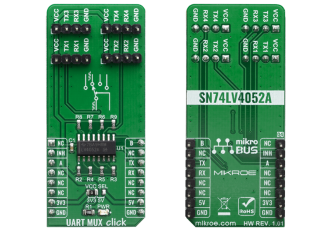
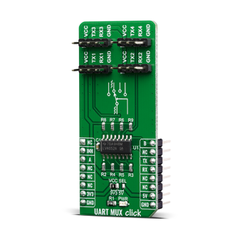
The UART Mux click is a Click board that switches the UART pins (RX and TX) from the mikroBUSâ„¢ to one of the four available outputs. It employs the SN74LV4052A, a Dual 4-Channel Multiplexer and Demultiplexer from Texas Instruments. It is designed for 2-V to 5.5-V VCC operation.

No Abuse Reported

Do you want to subscribe in order to receive notifications regarding "UART Mux click" changes.

Do you want to unsubscribe in order to stop receiving notifications regarding "UART Mux click" changes.

Do you want to report abuse regarding "UART Mux click".
  • mikroSDK Library 2.0.0.0
  • Comments (0)
DOWNLOAD LINK RELATED COMPILER CONTAINS
mikroBasic PRO for ARM
  • lib
  • src
  • exa
  • hlp
  • hex
  • sch
  • pcb
  • doc
mikroBasic PRO for AVR
  • lib
  • src
  • exa
  • hlp
  • hex
  • sch
  • pcb
  • doc
mikroBasic PRO for dsPIC30/33 & PIC24
  • lib
  • src
  • exa
  • hlp
  • hex
  • sch
  • pcb
  • doc
mikroBasic PRO for FT90x
  • lib
  • src
  • exa
  • hlp
  • hex
  • sch
  • pcb
  • doc
mikroBasic PRO for PIC
  • lib
  • src
  • exa
  • hlp
  • hex
  • sch
  • pcb
  • doc
mikroBasic PRO for PIC32
  • lib
  • src
  • exa
  • hlp
  • hex
  • sch
  • pcb
  • doc
mikroC PRO for ARM
  • lib
  • src
  • exa
  • hlp
  • hex
  • sch
  • pcb
  • doc
mikroC PRO for AVR
  • lib
  • src
  • exa
  • hlp
  • hex
  • sch
  • pcb
  • doc
mikroC PRO for dsPIC30/33 & PIC24
  • lib
  • src
  • exa
  • hlp
  • hex
  • sch
  • pcb
  • doc
mikroC PRO for FT90x
  • lib
  • src
  • exa
  • hlp
  • hex
  • sch
  • pcb
  • doc
mikroC PRO for PIC
  • lib
  • src
  • exa
  • hlp
  • hex
  • sch
  • pcb
  • doc
mikroC PRO for PIC32
  • lib
  • src
  • exa
  • hlp
  • hex
  • sch
  • pcb
  • doc
mikroPascal PRO for ARM
  • lib
  • src
  • exa
  • hlp
  • hex
  • sch
  • pcb
  • doc
mikroPascal PRO for AVR
  • lib
  • src
  • exa
  • hlp
  • hex
  • sch
  • pcb
  • doc
mikroPascal PRO for dsPIC30/33 & PIC24
  • lib
  • src
  • exa
  • hlp
  • hex
  • sch
  • pcb
  • doc
mikroPascal PRO for FT90x
  • lib
  • src
  • exa
  • hlp
  • hex
  • sch
  • pcb
  • doc
mikroPascal PRO for PIC
  • lib
  • src
  • exa
  • hlp
  • hex
  • sch
  • pcb
  • doc
mikroPascal PRO for PIC32
  • lib
  • src
  • exa
  • hlp
  • hex
  • sch
  • pcb
  • doc

mikroSDK Library Blog

UART Mux click

UART Mux click

Native view of the UART Mux click board.

View full image
UART Mux click

UART Mux click

Front and back view of the UART Mux click board.

View full image

Library Description

The library covers all the necessary functions that enables the usage of the UART Mux click board. User can write, read or check if there is a new byte received on all four channels that are available. Library also offers the functions taht allow user to inhibit or uninhibit the communication.

Key functions:

  • void uartmux_writeByte(uint8_t input) - Writes sinle byte
  • uint8_t uartmux_readByte() - Read received byte
  • uint8_t uartmux_byteReady() - Checks is there a new byte received

Examples description

The application is composed of three sections :

  • System Initialization - Initializes UART, GPIO and LOG structures, sets RST, CS and PWM pins as output.
  • Application Initialization - Initalizes UART driver, uninhibites communication and makes an initial log.
  • Application Task - (code snippet) This example demonstrates the use of UART Mux click board by eather sending or receiving the message on channel one of the device.
void applicationTask()
{
    char tmp;

// RECEIVER - UART polling
/*
    if ( 1 == uartmux_byteReadyChann1() )
    {
        tmp = uartmux_readByteChann1();
        mikrobus_logWrite( &tmp, _LOG_BYTE );
    }
*/
// TRANSMITER - TX each 2 sec

    for (tmp = 0; tmp < 9; tmp++)
    {
        uartmux_writeByteChann1( MESSAGE_DATA[tmp] );
    }

    Delay_ms(2000);

}

Other mikroE Libraries used in the example:

  • UART
  • Conversions

Additional notes and informations

Depending on the development board you are using, you may need USB UART clickUSB UART 2 click or RS232 click to connect to your PC, for development systems with no UART to USB interface available on the board. The terminal available in all MikroElektronika compilers, or any other terminal application of your choice, can be used to read the message.

ALSO FROM THIS AUTHOR

DC Motor 14

5

DC MOTOR 14 Click is a PWM chopper type brushed DC motor driver, labeled as TB67H450FNG. This IC includes one channel of motor output block, using a wide range of supply voltages, while delivering reasonably high current to the connected DC motors.

[Learn More]

GPS 3 click

5

Simple example which demonstrates usage of the GPS3 Click board with QUECTEL L80 GPS module. It displays a map of the world on the GLCD and shows the location of the GPS module on it.

[Learn More]

ROTARY Y Click

0

Rotary Click carries a 15-pulse incremental rotary encoder with detents, surrounded by a ring of 16 yellow LEDs. It’s a perfect solution for adding a precision input knob to your design. The encoder outputs A and B signals (out of phase to each other); the knob also acts as a push-button which sends an interrupt to the target board MCU. The LED ring is controlled through SPI lines (CS, SCK, MISO, MOSI). Rotary Click can be used with either a 3.3V or 5V power supply.

[Learn More]