TOP Contributors

  1. MIKROE (2784 codes)
  2. Alcides Ramos (392 codes)
  3. Shawon Shahryiar (307 codes)
  4. jm_palomino (123 codes)
  5. Bugz Bensce (97 codes)
  6. S P (73 codes)
  7. dany (71 codes)
  8. MikroBUS.NET Team (35 codes)
  9. NART SCHINACKOW (34 codes)
  10. Armstrong Subero (27 codes)

Most Downloaded

  1. Timer Calculator (140547 times)
  2. FAT32 Library (73037 times)
  3. Network Ethernet Library (58043 times)
  4. USB Device Library (48215 times)
  5. Network WiFi Library (43826 times)
  6. FT800 Library (43295 times)
  7. GSM click (30359 times)
  8. mikroSDK (28991 times)
  9. PID Library (27116 times)
  10. microSD click (26722 times)
Libstock prefers package manager

Package Manager

We strongly encourage users to use Package manager for sharing their code on Libstock website, because it boosts your efficiency and leaves the end user with no room for error. [more info]

< Back
mikroSDK Library

I2C to SPI click

Rating:

5

Author: MIKROE

Last Updated: 2019-09-13

Package Version: 1.0.0.0

mikroSDK Library: 1.0.0.0

Category: I2C

Downloaded: 2472 times

Not followed.

License: MIT license  

I2C to SPI Click is an all-in-one solution which allows serving as an interface between a standard I2C-bus of a microcontroller and an SPI bus, which allows the microcontroller to communicate directly with SPI devices through its I2C-bus.

No Abuse Reported

Do you want to subscribe in order to receive notifications regarding "I2C to SPI click" changes.

Do you want to unsubscribe in order to stop receiving notifications regarding "I2C to SPI click" changes.

Do you want to report abuse regarding "I2C to SPI click".
  • mikroSDK Library 2.0.0.0
  • Comments (0)

mikroSDK Library Blog

I2C to SPI Click

I2C to SPI Click

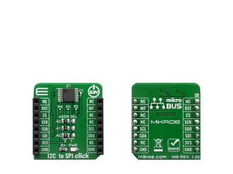
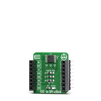
Native view of the I2C to SPI Click board.

View full image
I2C to SPI Click

I2C to SPI Click

Front and back view of the I2C to SPI Click board.

View full image

Library Description

The library covers all the necessary functions to control I2C to SPI click board. A library performs interface between a standard I2C-bus of a microcontroller and an SPI bus.

Key functions:

  • void i2ctospi_spiWriteByte( uint8_t slaveDevice, uint8_t functionId, uint8_t regAddr, uint8_t writeData ) - Generic SPI writes the byte of data to data buffer function.
  • uint8_t i2ctospi_spiReadByte( uint8_t slaveDevice, uint8_t functionId, uint8_t regAddr ) - Generic SPI read the byte of data from data buffer function.
  • void i2ctospi_configSPI( uint8_t configData ) - Configure SPI Interface function.

Examples description

The application is composed of the three sections :

  • System Initialization - Initializes GPIO, SPI and LOG structures, sets RST and CS pins as output and INT pin as an input.
  • Application Initialization - Initialization driver enable's - I2C, hardware reset, SS0 ( CS ) configured to be used as slave select outputs, set the configuration of SPI: order MSB first, clock Idle low, leading-edge transition, SPI clock rate to 115kHz, set SPI EEPROM write enable SS0, clear  interrupt, clear RT5 register, sets starting time: hours, minutes and seconds ( enable counting ), also write log.
  • Application Task - This is an example which demonstrates the use of RTC 5 click is wired to I2C to SPI click board. I2C to SPI click communicates with register via the I2C interface, serve as an interface between a standard I2C-bus of a microcontroller and an SPI bus. RTC 5 click communicates with register via SPI interface. In this examples, we display RTC time which we received reading from the target register address of MCP79510 chip on RTC 5 click board via I2C interface of I2C to SPI click board. Results are being sent to the Usart Terminal where you can track their changes. All data logs write on usb uart changes for every 1 sec.
void applicationTask()
{
    timeSeconds = _rtc5GetTimeSeconds();
    Delay_1ms();
    timeMinutes = _rtc5GetTimeMinutes();
    Delay_1ms();
    timeHours = _rtc5GetTimeHours();
    Delay_1ms();

    if ( timeSecondsNew != timeSeconds )
    {
        mikrobus_logWrite( " Time :  ", _LOG_TEXT );

        _displayLogUart( timeHours );
        mikrobus_logWrite( ":", _LOG_TEXT );

        _displayLogUart( timeMinutes );
        mikrobus_logWrite( ":", _LOG_TEXT );

        _displayLogUart( timeSeconds );
        mikrobus_logWrite( "", _LOG_LINE );
 
        mikrobus_logWrite( "------------------", _LOG_LINE );

        timeSecondsNew = timeSeconds;
    }

    Delay_1ms();
}

Additional Functions :

  • void _displayLogUart( uint8_t value ) - Write the value of time or date as a two-digit number.
  • void _rtc5Clear() - Clear RTCC and SRAM memory of RTC 5 click.
  • void _rtc5SetTimeSeconds( uint8_t seconds ) - Set the seconds and enable counting.
  • uint8_t _rtc5GetTimeSeconds() - Get the seconds.
  • void _rtc5SetTimeMinutes( uint8_t minutes ) - Set the minutes.
  • uint8_t _rtc5GetTimeMinutes() - Get the minutes.
  • void _rtc5SetTimeHours( uint8_t hours ) - Set the hours.
  • uint8_t _rtc5GetTimeHours() - Get the hours.

Other mikroE Libraries used in the example:

  • I2C
  • UART
  • Conversions

Additional notes and informations

Depending on the development board you are using, you may need USB UART clickUSB UART 2 click or RS232 click to connect to your PC, for development systems with no UART to USB interface available on the board. The terminal available in all MikroElektronika compilers, or any other terminal application of your choice, can be used to read the message.

ALSO FROM THIS AUTHOR

Charger 6 Click

0

Charger 6 Click is a compact add-on board that represents a single-cell battery charger. This board features the BQ25601, an I2C controlled battery charger for high input voltage and narrow voltage DC power path management from Texas Instruments. This buck charger supports USB, and it’s optimized for USB voltage input. The low impedance power path optimizes switch-mode operation efficiency, reduces battery charging time, and extends battery life during discharge. It also has a programmable current limiting, allowing it to use an external power supply rated up to 13.5V. This Click board™ is suitable as a Li-Ion and Li-polymer battery charger for portable devices and accessories, power tools, and more.

[Learn More]

Expand 12 Click

0

Expand 12 Click is a compact add-on board that contains a multi-port I/O expander. This board features the MAX7300, a general-purpose I/O expander providing remote I/O expansion for most MCU’s families from Maxim Integrated, now part of Analog Devices. The MAX7300 comes in a 28-port configuration and allows easy addition of I/O through a standard I2C serial interface. Each port is user-configurable to either a logic input or logic output, capable of sinking 10mA and sourcing 4.5mA.

[Learn More]

H-Bridge Driver Click

0

H-Bridge Driver Click is a compact add-on board that contains an H-bridge gate driver, also known as a full-bridge pre-driver. This board features the MC33883, an H-Bridge gate driver with an integrated charge pump and independent high and low side gate drive channels from NXP Semiconductors.

[Learn More]