TOP Contributors

  1. MIKROE (2784 codes)
  2. Alcides Ramos (396 codes)
  3. Shawon Shahryiar (307 codes)
  4. jm_palomino (127 codes)
  5. Bugz Bensce (97 codes)
  6. S P (73 codes)
  7. dany (71 codes)
  8. MikroBUS.NET Team (35 codes)
  9. NART SCHINACKOW (34 codes)
  10. Armstrong Subero (27 codes)

Most Downloaded

  1. Timer Calculator (140717 times)
  2. FAT32 Library (73186 times)
  3. Network Ethernet Library (58132 times)
  4. USB Device Library (48290 times)
  5. Network WiFi Library (43927 times)
  6. FT800 Library (43416 times)
  7. GSM click (30419 times)
  8. mikroSDK (29118 times)
  9. PID Library (27132 times)
  10. microSD click (26779 times)
Libstock prefers package manager

Package Manager

We strongly encourage users to use Package manager for sharing their code on Libstock website, because it boosts your efficiency and leaves the end user with no room for error. [more info]

< Back
mikroSDK Library

H-Bridge 4 click

Rating:

5

Author: MIKROE

Last Updated: 2019-10-25

Package Version: 1.0.0.0

mikroSDK Library: 1.0.0.0

Category: Brushed

Downloaded: 3651 times

Not followed.

License: MIT license  

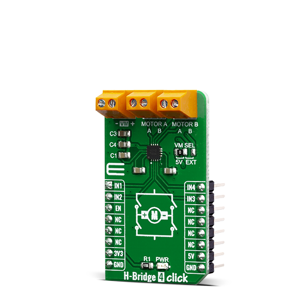
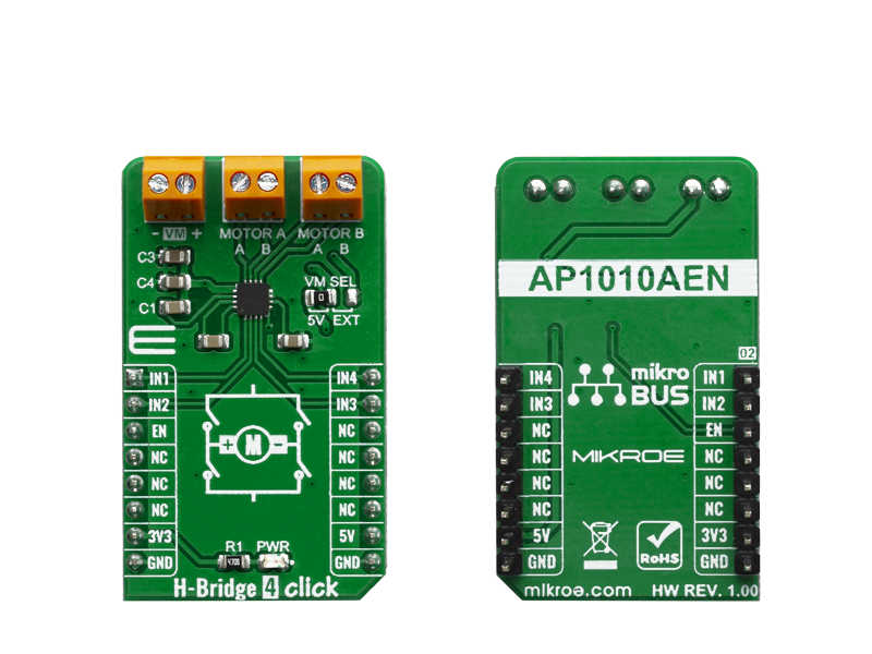
H-Bridge 4 Click is a Click board that contains the AP1010AEN, which is a two channel H-Bridge motor driver compatible with a motor operating voltage up to 18V and can drive two DC motors or one stepper motor.

No Abuse Reported

Do you want to subscribe in order to receive notifications regarding "H-Bridge 4 click" changes.

Do you want to unsubscribe in order to stop receiving notifications regarding "H-Bridge 4 click" changes.

Do you want to report abuse regarding "H-Bridge 4 click".

  • mikroSDK Library 2.0.0.0
  • Comments (0)
DOWNLOAD LINK RELATED COMPILER CONTAINS
mikroBasic PRO for ARM
  • lib
  • src
  • exa
  • hlp
  • hex
  • sch
  • pcb
  • doc
mikroBasic PRO for AVR
  • lib
  • src
  • exa
  • hlp
  • hex
  • sch
  • pcb
  • doc
mikroBasic PRO for dsPIC30/33 & PIC24
  • lib
  • src
  • exa
  • hlp
  • hex
  • sch
  • pcb
  • doc
mikroBasic PRO for FT90x
  • lib
  • src
  • exa
  • hlp
  • hex
  • sch
  • pcb
  • doc
mikroBasic PRO for PIC
  • lib
  • src
  • exa
  • hlp
  • hex
  • sch
  • pcb
  • doc
mikroBasic PRO for PIC32
  • lib
  • src
  • exa
  • hlp
  • hex
  • sch
  • pcb
  • doc
mikroC PRO for ARM
  • lib
  • src
  • exa
  • hlp
  • hex
  • sch
  • pcb
  • doc
mikroC PRO for AVR
  • lib
  • src
  • exa
  • hlp
  • hex
  • sch
  • pcb
  • doc
mikroC PRO for dsPIC30/33 & PIC24
  • lib
  • src
  • exa
  • hlp
  • hex
  • sch
  • pcb
  • doc
mikroC PRO for FT90x
  • lib
  • src
  • exa
  • hlp
  • hex
  • sch
  • pcb
  • doc
mikroC PRO for PIC
  • lib
  • src
  • exa
  • hlp
  • hex
  • sch
  • pcb
  • doc
mikroC PRO for PIC32
  • lib
  • src
  • exa
  • hlp
  • hex
  • sch
  • pcb
  • doc
mikroPascal PRO for ARM
  • lib
  • src
  • exa
  • hlp
  • hex
  • sch
  • pcb
  • doc
mikroPascal PRO for AVR
  • lib
  • src
  • exa
  • hlp
  • hex
  • sch
  • pcb
  • doc
mikroPascal PRO for dsPIC30/33 & PIC24
  • lib
  • src
  • exa
  • hlp
  • hex
  • sch
  • pcb
  • doc
mikroPascal PRO for FT90x
  • lib
  • src
  • exa
  • hlp
  • hex
  • sch
  • pcb
  • doc
mikroPascal PRO for PIC
  • lib
  • src
  • exa
  • hlp
  • hex
  • sch
  • pcb
  • doc
mikroPascal PRO for PIC32
  • lib
  • src
  • exa
  • hlp
  • hex
  • sch
  • pcb
  • doc

mikroSDK Library Blog

H-Bridge 4 Click

H-Bridge 4 Click

Native view of the H-Bridge 4 Click board.

View full image
H-Bridge 4 Click

H-Bridge 4 Click

Front and back view of the H-Bridge 4 Click board.

View full image

Library Description

The library covers all the necessary functions to control H-Bridge 4 click board. The H-Bridge 4 click communicates with the target board through the AN, INT, PWM, RST and CS lines on MikroBUS. This library offers functions for setting or clearing of any and every of the five pins used for communication, also user can use functions that enable or disable clockwise or counter-clockwise motion, as well as standby mode and brake for both channels.

Key functions:

  • void hbridge4_motorAStandby() - Function is used to put motor A into standby.
  • void hbridge4_motorACW() - Function is used to put motor A into clockwise motion.
  • void hbridge4_motorABrake() - Function is used to brake motor A to a halt.

Examples description

The application is composed of three sections :

  • System Initialization - Initializes GPIO and LOG structures, sets AN, INT, PWM, RST and CS pins as output.
  • Application Initialization - Initialization driver enables GPIO and also starts write log.
  • Application Task - (code snippet) This example demonstrates the use of H-Bridge 4 click board by putting A motor in standby mode, then spining it in clockwise direction and applying brake function, and then spining it in counter-clockwise direction and applying brake function again.
void applicationTask()
{
    mikrobus_logWrite( "The motor A is in standby mode", _LOG_LINE );
    hbridge4_motorAStandby();
    Delay_ms( 100 );
    mikrobus_logWrite( "The motor A turns clockwise", _LOG_LINE );
    hbridge4_motorACW();
    Delay_ms( 2000 );
    mikrobus_logWrite( "The motor A applies brake", _LOG_LINE );
    hbridge4_motorABrake();
    Delay_ms( 1000 );
    mikrobus_logWrite( "The motor A turns counter-clockwise", _LOG_LINE );
    hbridge4_motorACCW();
    Delay_ms( 2000 );
    mikrobus_logWrite( "The motor A applies brake", _LOG_LINE );
    hbridge4_motorABrake();
    Delay_ms( 1000 );
}

Other mikroE Libraries used in the example:

  • UART

Additional notes and informations

Depending on the development board you are using, you may need USB UART clickUSB UART 2 click or RS232 click to connect to your PC, for development systems with no UART to USB interface available on the board. The terminal available in all MikroElektronika compilers, or any other terminal application of your choice, can be used to read the message.

ALSO FROM THIS AUTHOR

BarGraph 3 click

6

BarGraph 3 click is equipped with a five-segment LED bar graph display, notable for its strong and reliable illumination of the segments.

[Learn More]

3D Hall Click

0

This application use to determine angle position

[Learn More]

DIGI POT 5 Click

0

DIGI POT 5 Click is a digitally controlled quad potentiometer, with the resistance of 10KΩ. It has an 8bit wiper step resolution, which allows the wiper to take 257 different discrete positions (across 256 internal resistors). The digital wiper position can be controlled via the SPI interface.

[Learn More]