
We strongly encourage users to use Package manager for sharing their code on Libstock website, because it boosts your efficiency and leaves the end user with no room for error. [more info]

Rating:
Author: MIKROE
Last Updated: 2016-02-18
Package Version: 1.0.0.0
Category: RFid
Downloaded: 7306 times
Followed by: 3 users
License: MIT license
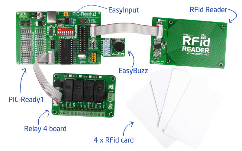
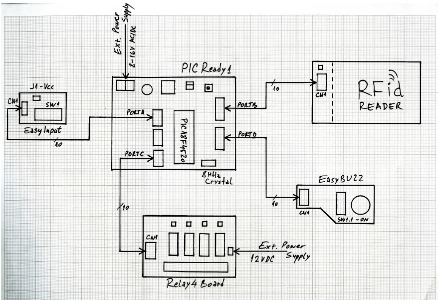
Using PIC-Ready1 with PIC18F4520, RFid reader, Relay 4 board, along with EasyInput and EasyBuzz we have created a simple RFid lock that controls 4 separate relays with RFid cards. And it will cost you less than $100 USD!
Do you want to subscribe in order to receive notifications regarding "RFid Lock with 4 Relays" changes.
Do you want to unsubscribe in order to stop receiving notifications regarding "RFid Lock with 4 Relays" changes.
Do you want to report abuse regarding "RFid Lock with 4 Relays".
| DOWNLOAD LINK | RELATED COMPILER | CONTAINS |
|---|---|---|
| 1366714313_rfid_lock_with_4_mikroc_pic.rar [204.86KB] | mikroC PRO for PIC |
|
| 1366714331_rfid_lock_with_4_mikrobasic_pic.rar [204.59KB] | mikroBasic PRO for PIC |
|
| 1366714348_rfid_lock_with_4_mikropascal_pic.rar [204.81KB] | mikroPascal PRO for PIC |
|

At least once in our lives we have come across some kind of RFid locks in homes, offices, elevators or hotels. Some of you may have been inspired to build your own version of it for your home or as a final product. We will show you how you can do this in a blink of an eye. Using PIC-Ready1 with PIC18F4520, RFid reader, Relay 4 board, along with EasyInput and EasyBuzz we have created a RFid lock that controls 4 separate relays with RFid cards. And it will cost you less than $100!
Before you can use it, you must program the board to recognize your RFid cards, and assign them to each relay separately.

Source code of this project is provided for free, so you can modify it to suit your needs. Since PIC18F4520 comes preprogrammed with free UART Bootloader, you won’t have to spend a dollar more on external programmers. You can modify the project as much as you like, and expand this basic functionality with your own implementation ideas.


