TOP Contributors

  1. MIKROE (2784 codes)
  2. Alcides Ramos (387 codes)
  3. Shawon Shahryiar (307 codes)
  4. jm_palomino (120 codes)
  5. Bugz Bensce (97 codes)
  6. S P (73 codes)
  7. dany (71 codes)
  8. MikroBUS.NET Team (35 codes)
  9. NART SCHINACKOW (34 codes)
  10. Armstrong Subero (27 codes)

Most Downloaded

  1. Timer Calculator (140168 times)
  2. FAT32 Library (72621 times)
  3. Network Ethernet Library (57641 times)
  4. USB Device Library (47955 times)
  5. Network WiFi Library (43553 times)
  6. FT800 Library (42942 times)
  7. GSM click (30140 times)
  8. mikroSDK (28669 times)
  9. PID Library (27056 times)
  10. microSD click (26552 times)
Libstock prefers package manager

Package Manager

We strongly encourage users to use Package manager for sharing their code on Libstock website, because it boosts your efficiency and leaves the end user with no room for error. [more info]

< Back
mikroSDK Library

CAN FD click

Rating:

5

Author: MIKROE

Last Updated: 2020-01-24

Package Version: 1.0.0.0

mikroSDK Library: 1.0.0.0

Category: CAN

Downloaded: 4161 times

Not followed.

License: MIT license  

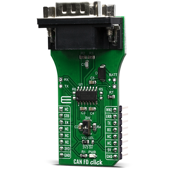
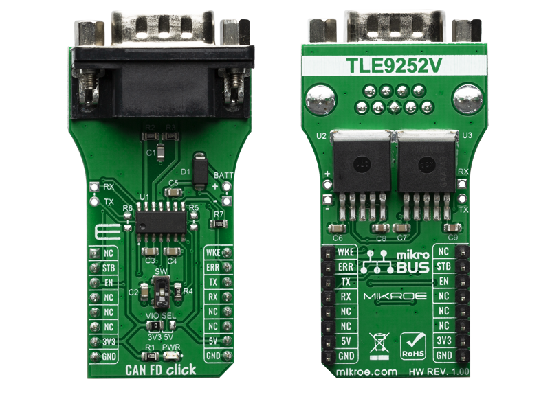
CAN FD Click is a transceiver designed for HS CAN networks up to 5 Mbit/s in automotive and industrial applications. As an interface between the physical bus layer and the CAN protocol controller, the TLE9252V drives the signals to the bus and protects the microcontroller against interferences generated within the network.

No Abuse Reported

Do you want to subscribe in order to receive notifications regarding "CAN FD click" changes.

Do you want to unsubscribe in order to stop receiving notifications regarding "CAN FD click" changes.

Do you want to report abuse regarding "CAN FD click".

  • mikroSDK Library 2.0.0.0
  • Comments (0)
DOWNLOAD LINK RELATED COMPILER CONTAINS
mikroBasic PRO for ARM
  • lib
  • src
  • exa
  • hlp
  • hex
  • sch
  • pcb
  • doc
mikroBasic PRO for AVR
  • lib
  • src
  • exa
  • hlp
  • hex
  • sch
  • pcb
  • doc
mikroBasic PRO for dsPIC30/33 & PIC24
  • lib
  • src
  • exa
  • hlp
  • hex
  • sch
  • pcb
  • doc
mikroBasic PRO for FT90x
  • lib
  • src
  • exa
  • hlp
  • hex
  • sch
  • pcb
  • doc
mikroBasic PRO for PIC
  • lib
  • src
  • exa
  • hlp
  • hex
  • sch
  • pcb
  • doc
mikroBasic PRO for PIC32
  • lib
  • src
  • exa
  • hlp
  • hex
  • sch
  • pcb
  • doc
mikroC PRO for ARM
  • lib
  • src
  • exa
  • hlp
  • hex
  • sch
  • pcb
  • doc
mikroC PRO for AVR
  • lib
  • src
  • exa
  • hlp
  • hex
  • sch
  • pcb
  • doc
mikroC PRO for dsPIC30/33 & PIC24
  • lib
  • src
  • exa
  • hlp
  • hex
  • sch
  • pcb
  • doc
mikroC PRO for FT90x
  • lib
  • src
  • exa
  • hlp
  • hex
  • sch
  • pcb
  • doc
mikroC PRO for PIC
  • lib
  • src
  • exa
  • hlp
  • hex
  • sch
  • pcb
  • doc
mikroC PRO for PIC32
  • lib
  • src
  • exa
  • hlp
  • hex
  • sch
  • pcb
  • doc
mikroPascal PRO for ARM
  • lib
  • src
  • exa
  • hlp
  • hex
  • sch
  • pcb
  • doc
mikroPascal PRO for AVR
  • lib
  • src
  • exa
  • hlp
  • hex
  • sch
  • pcb
  • doc
mikroPascal PRO for dsPIC30/33 & PIC24
  • lib
  • src
  • exa
  • hlp
  • hex
  • sch
  • pcb
  • doc
mikroPascal PRO for FT90x
  • lib
  • src
  • exa
  • hlp
  • hex
  • sch
  • pcb
  • doc
mikroPascal PRO for PIC
  • lib
  • src
  • exa
  • hlp
  • hex
  • sch
  • pcb
  • doc
mikroPascal PRO for PIC32
  • lib
  • src
  • exa
  • hlp
  • hex
  • sch
  • pcb
  • doc

mikroSDK Library Blog

CAN FD click

CAN FD click

Native view of the CAN FD click board.

View full image
CAN FD click

CAN FD click

Front and back view of the CAN FD click board.

View full image

Library Description

The library covers all the necessary functions to control CAN FD click board. Library performs a standard UART communication.

Key functions:

  • canfd_byte_ready( ) - Write Single Byte
  • uint8_t canfd_read_byte( ) - Read Single Byte.
  • void canfd_set_operating_mode ( uint8_t op_mode ) - Set operating mode function.

Examples description

The application is composed of three sections :

  • System Initialization - Initializes UART, sets ERR ( INT ) pin as input and STB ( RST ) and EN ( CS ) pins as output, begins to write a log.
  • Application Initialization - Initialization driver enables - UART, performs an app mode, also write log.
  • Application Task - (code snippet) This is an example that demonstrates the use of the CAN FD click board. This application task writes message data via UART. In the second case, checks if new data byte have received in RX buffer ( ready for reading ), and if ready than reads one byte from RX buffer. Results are being sent to the Usart Terminal where you can track their changes.
void application_task ( )
{
    char tmp;
    uint8_t drdy_flag;

    if ( app_mode == APP_MODE_RECEIVER )
    {
        // RECEIVER - UART polling

        drdy_flag = canfd_byte_ready( );

        if ( 1 == drdy_flag )
        {
            tmp = canfd_read_byte( );
            mikrobus_logWrite( &tmp, _LOG_BYTE );
        }
    }
    else
    {
        // TRANSMITER - TX each 2 sec
        mikrobus_logWrite( " TX data: ", _LOG_TEXT );
        Delay_ms( 1000 );
        
        for ( tmp = 0; tmp < 9; tmp++ )
        {
            canfd_write_byte( demo_message_data[ tmp ] );
            mikrobus_logWrite( &demo_message_data[ tmp ], _LOG_BYTE );
            Delay_ms( 200 );
        }

        mikrobus_logWrite( "------------------", _LOG_LINE );
        Delay_ms( 2000 );
    }
}

Other mikroE Libraries used in the example:

  • UART

Additional notes and informations

Depending on the development board you are using, you may need USB UART clickUSB UART 2 click or RS232 click to connect to your PC, for development systems with no UART to USB interface available on the board. The terminal available in all MikroElektronika compilers, or any other terminal application of your choice, can be used to read the message.

ALSO FROM THIS AUTHOR

Matrix G Click

0

Matrix G Click is a mikroBUS add-on board with two green 5x7 matrices driven by two MAX7219 8-bit LED Display Drivers. The active area of each matrix is 7.62mm high and 5.08 mm wide. 7x5 is a standard resolution for displaying ASCII characters, so the Click is essentially a dual-character display capable of showing letters in more readable typefaces compared to a 14-segment display. The Click communicates with the target MCU through the mikroBUS SPI interface with two separate Chip Select lines for each matrix (CSL for the left, CSR for the right). This board is designed to use a 5V power supply.

[Learn More]

RS485 Isolator Click

0

RS485 Isolator Click is an RS485 communication isolator and carries the ADM2682EBRIZ, a 5 kV rms signal and power isolated RS-485 transceiver.

[Learn More]

CapSense 2 Click

0

CapSense 2 Click is a compact add-on board that easily integrates projected capacitive touch into user's applications. This board features the CAP1114, a multi-channel capacitive touch sensor that takes human body capacitance as an input and directly provides the real-time sensor information via the I2C serial interface from Microchip. This board contains capacitive sensing elements, a 7-segment slider, two buttons, and four LED indicators that visually detect the activation on some of these parts. This Click board™ offers reliable and accurate sensing for any application that uses capacitive touch sensing functions.

[Learn More]