TOP Contributors

  1. MIKROE (2784 codes)
  2. Alcides Ramos (405 codes)
  3. Shawon Shahryiar (307 codes)
  4. jm_palomino (133 codes)
  5. Bugz Bensce (97 codes)
  6. S P (73 codes)
  7. dany (71 codes)
  8. MikroBUS.NET Team (35 codes)
  9. NART SCHINACKOW (34 codes)
  10. Armstrong Subero (27 codes)

Most Downloaded

  1. Timer Calculator (141856 times)
  2. FAT32 Library (75023 times)
  3. Network Ethernet Library (59335 times)
  4. USB Device Library (49335 times)
  5. Network WiFi Library (45147 times)
  6. FT800 Library (44691 times)
  7. GSM click (31297 times)
  8. mikroSDK (30249 times)
  9. microSD click (27681 times)
  10. PID Library (27570 times)
Libstock prefers package manager

Package Manager

We strongly encourage users to use Package manager for sharing their code on Libstock website, because it boosts your efficiency and leaves the end user with no room for error. [more info]

< Back
mikroSDK Library

CAN FD 3 click

Rating:

5

Author: MIKROE

Last Updated: 2020-03-06

Package Version: 1.0.0.0

mikroSDK Library: 1.0.0.0

Category: CAN

Downloaded: 3650 times

Not followed.

License: MIT license  

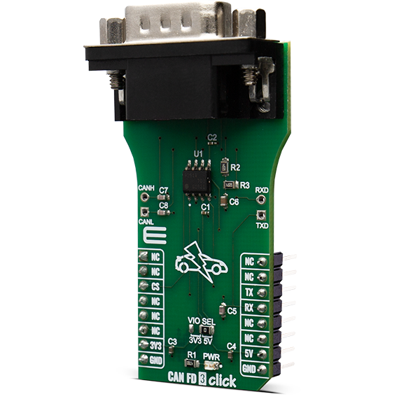
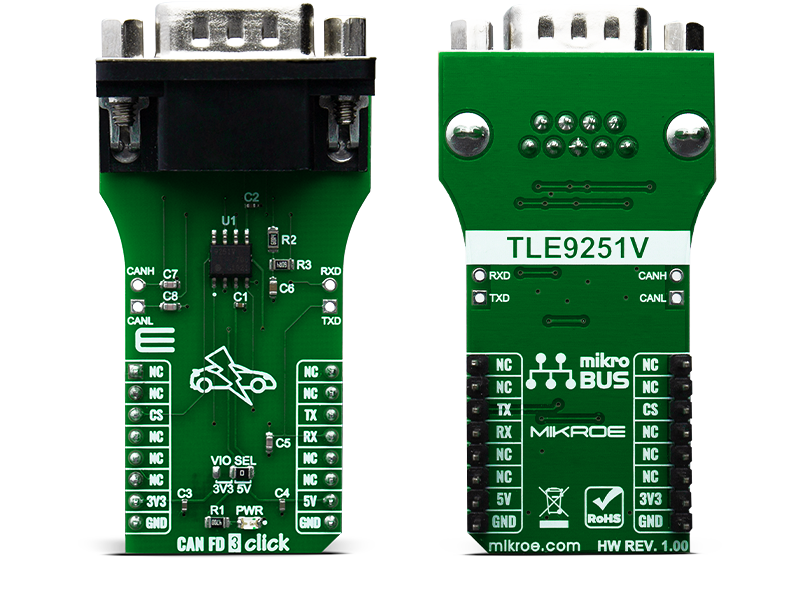
CAN FD 3 Click is a add-on board based on TLE9251V CAN network transceiver, designed for HS CAN networks up to 5 Mbit/s in automotive and industrial applications.

No Abuse Reported

Do you want to subscribe in order to receive notifications regarding "CAN FD 3 click" changes.

Do you want to unsubscribe in order to stop receiving notifications regarding "CAN FD 3 click" changes.

Do you want to report abuse regarding "CAN FD 3 click".

  • mikroSDK Library 2.0.0.0
  • Comments (0)
DOWNLOAD LINK RELATED COMPILER CONTAINS
mikroBasic PRO for ARM
  • lib
  • src
  • exa
  • hlp
  • hex
  • sch
  • pcb
  • doc
mikroBasic PRO for AVR
  • lib
  • src
  • exa
  • hlp
  • hex
  • sch
  • pcb
  • doc
mikroBasic PRO for dsPIC30/33 & PIC24
  • lib
  • src
  • exa
  • hlp
  • hex
  • sch
  • pcb
  • doc
mikroBasic PRO for FT90x
  • lib
  • src
  • exa
  • hlp
  • hex
  • sch
  • pcb
  • doc
mikroBasic PRO for PIC
  • lib
  • src
  • exa
  • hlp
  • hex
  • sch
  • pcb
  • doc
mikroBasic PRO for PIC32
  • lib
  • src
  • exa
  • hlp
  • hex
  • sch
  • pcb
  • doc
mikroC PRO for ARM
  • lib
  • src
  • exa
  • hlp
  • hex
  • sch
  • pcb
  • doc
mikroC PRO for AVR
  • lib
  • src
  • exa
  • hlp
  • hex
  • sch
  • pcb
  • doc
mikroC PRO for dsPIC30/33 & PIC24
  • lib
  • src
  • exa
  • hlp
  • hex
  • sch
  • pcb
  • doc
mikroC PRO for FT90x
  • lib
  • src
  • exa
  • hlp
  • hex
  • sch
  • pcb
  • doc
mikroC PRO for PIC
  • lib
  • src
  • exa
  • hlp
  • hex
  • sch
  • pcb
  • doc
mikroC PRO for PIC32
  • lib
  • src
  • exa
  • hlp
  • hex
  • sch
  • pcb
  • doc
mikroPascal PRO for ARM
  • lib
  • src
  • exa
  • hlp
  • hex
  • sch
  • pcb
  • doc
mikroPascal PRO for AVR
  • lib
  • src
  • exa
  • hlp
  • hex
  • sch
  • pcb
  • doc
mikroPascal PRO for dsPIC30/33 & PIC24
  • lib
  • src
  • exa
  • hlp
  • hex
  • sch
  • pcb
  • doc
mikroPascal PRO for FT90x
  • lib
  • src
  • exa
  • hlp
  • hex
  • sch
  • pcb
  • doc
mikroPascal PRO for PIC
  • lib
  • src
  • exa
  • hlp
  • hex
  • sch
  • pcb
  • doc
mikroPascal PRO for PIC32
  • lib
  • src
  • exa
  • hlp
  • hex
  • sch
  • pcb
  • doc

mikroSDK Library Blog

CAN FD 3 Click

CAN FD 3 Click

Native view of the CAN FD 3 Click board.

View full image
CAN FD 3 Click

CAN FD 3 Click

Front and back view of the CLICK_NAME board.

View full image

Library Description

Library provides functions for communication via UART module, and a function for controlling cs pin, which sets device mode.

Key functions:

  • void canfd3_write_byte ( uint8_t input ) - Writes single byte of data
  • uint8_t canfd3_read_byte( ) - Reads single byte of data
  • uint8_t canfd3_byte_ready ( ) - Checks if new data ic received
  • void canfd3_set_cs_pin ( uint8_t mode ) - Sets state of the CS pin

Examples description

The application is composed of three sections :

  • System Initialization - Intializes UART module
  • Application Initialization - Driver intialization
  • Application Task - Choose one mode (read or write) of task. If you reading it checks if data is ready to be read and then reads one byte and if you are wiriting send data via UART.
void application_task ( )
{
    float read_data;
    char txt_out[ 30 ];

    read_data = thermo17_read_temp( THERMO17_TEMPERATURE_LOCAL );
    FloatToStr( read_data, txt_out );
    mikrobus_logWrite( " - LOCAL: ", _LOG_TEXT );
    mikrobus_logWrite( txt_out, _LOG_LINE );

    Delay_ms( 100 );

    read_data = thermo17_read_temp( THERMO17_TEMPERATURE_REMOTE );
    FloatToStr( read_data, txt_out );
    mikrobus_logWrite( " - REMOTE: ", _LOG_TEXT );
    mikrobus_logWrite( txt_out, _LOG_LINE );
    
    Delay_ms( 100 );
    mikrobus_logWrite( " ******************** ", _LOG_LINE );
    Delay_ms( 1000 );
}

Other mikroE Libraries used in the example:

  • UART

Additional notes and informations

Depending on the development board you are using, you may need USB UART clickUSB UART 2 click or RS232 click to connect to your PC, for development systems with no UART to USB interface available on the board. The terminal available in all MikroElektronika compilers, or any other terminal application of your choice, can be used to read the message.

ALSO FROM THIS AUTHOR

Dot Matrix R click

5

Dot Matrix R Click is a display device Click board based on a four-digit dot matrix display module, labeled as HCMS-3906. The module holds four 5x7 dot matrices, with very closely spaced, bright red pixel elements. Characters are very clearly displayed as a result.

[Learn More]

Stepper 22 Click

0

Stepper 22 Click is a compact add-on board designed for precise motion control of bipolar stepper motors and brushed DC motors. This board features the DRV8711, a bipolar stepper motor gate driver from Texas Instruments, which uses external N-channel MOSFETs to drive motors with up to 5A of output current. The board features a wide range of microstepping options from full-step to 1/256-step, adaptive blanking time, and various current decay modes, ensuring smooth and accurate motor operation. Control is achieved via a standard SPI interface and STEP/DIR inputs, with additional management through an onboard I2C-configurable GPIO expander.

[Learn More]

ADC 5 Click

0

ADC 5 Click is a Click board™ used to sample an analog voltage on the input and convert it to a digital information. ADC 5 Click is equipped with the ADC121S021, a low power, single channel 12-bit CMOS analog to digital converter (ADC), with a high-speed serial interface.

[Learn More]