TOP Contributors

  1. MIKROE (2779 codes)
  2. Alcides Ramos (376 codes)
  3. Shawon Shahryiar (307 codes)
  4. jm_palomino (118 codes)
  5. Bugz Bensce (97 codes)
  6. S P (73 codes)
  7. dany (71 codes)
  8. MikroBUS.NET Team (35 codes)
  9. NART SCHINACKOW (34 codes)
  10. Armstrong Subero (27 codes)

Most Downloaded

  1. Timer Calculator (139566 times)
  2. FAT32 Library (72041 times)
  3. Network Ethernet Library (57255 times)
  4. USB Device Library (47615 times)
  5. Network WiFi Library (43219 times)
  6. FT800 Library (42566 times)
  7. GSM click (29930 times)
  8. mikroSDK (28292 times)
  9. PID Library (26933 times)
  10. microSD click (26309 times)
Libstock prefers package manager

Package Manager

We strongly encourage users to use Package manager for sharing their code on Libstock website, because it boosts your efficiency and leaves the end user with no room for error. [more info]

< Back
mikroSDK Library

Analog Mux click

Rating:

5

Author: MIKROE

Last Updated: 2020-05-13

Package Version: 1.0.0.0

mikroSDK Library: 1.0.0.0

Category: Port expander

Downloaded: 2354 times

Not followed.

License: MIT license  

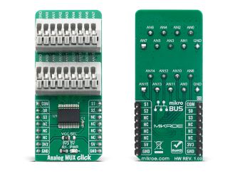
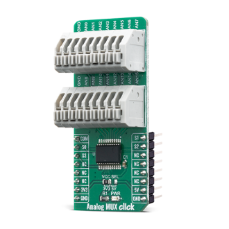
Analog MUX click is a Click board that switches one of the sixteen inputs to one output. It employs the CD74HC4067, a High-Speed CMOS Logic 16-Channel Analog Multiplexer/Demultiplexer, produced by Texas Instruments.

No Abuse Reported

Do you want to subscribe in order to receive notifications regarding "Analog Mux click" changes.

Do you want to unsubscribe in order to stop receiving notifications regarding "Analog Mux click" changes.

Do you want to report abuse regarding "Analog Mux click".
  • mikroSDK Library 2.0.0.0
  • Comments (0)
DOWNLOAD LINK RELATED COMPILER CONTAINS
mikroBasic PRO for ARM
  • lib
  • src
  • exa
  • hlp
  • hex
  • sch
  • pcb
  • doc
mikroBasic PRO for AVR
  • lib
  • src
  • exa
  • hlp
  • hex
  • sch
  • pcb
  • doc
mikroBasic PRO for dsPIC30/33 & PIC24
  • lib
  • src
  • exa
  • hlp
  • hex
  • sch
  • pcb
  • doc
mikroBasic PRO for FT90x
  • lib
  • src
  • exa
  • hlp
  • hex
  • sch
  • pcb
  • doc
mikroBasic PRO for PIC
  • lib
  • src
  • exa
  • hlp
  • hex
  • sch
  • pcb
  • doc
mikroBasic PRO for PIC32
  • lib
  • src
  • exa
  • hlp
  • hex
  • sch
  • pcb
  • doc
mikroC PRO for ARM
  • lib
  • src
  • exa
  • hlp
  • hex
  • sch
  • pcb
  • doc
mikroC PRO for AVR
  • lib
  • src
  • exa
  • hlp
  • hex
  • sch
  • pcb
  • doc
mikroC PRO for dsPIC30/33 & PIC24
  • lib
  • src
  • exa
  • hlp
  • hex
  • sch
  • pcb
  • doc
mikroC PRO for FT90x
  • lib
  • src
  • exa
  • hlp
  • hex
  • sch
  • pcb
  • doc
mikroC PRO for PIC
  • lib
  • src
  • exa
  • hlp
  • hex
  • sch
  • pcb
  • doc
mikroC PRO for PIC32
  • lib
  • src
  • exa
  • hlp
  • hex
  • sch
  • pcb
  • doc
mikroPascal PRO for ARM
  • lib
  • src
  • exa
  • hlp
  • hex
  • sch
  • pcb
  • doc
mikroPascal PRO for AVR
  • lib
  • src
  • exa
  • hlp
  • hex
  • sch
  • pcb
  • doc
mikroPascal PRO for dsPIC30/33 & PIC24
  • lib
  • src
  • exa
  • hlp
  • hex
  • sch
  • pcb
  • doc
mikroPascal PRO for FT90x
  • lib
  • src
  • exa
  • hlp
  • hex
  • sch
  • pcb
  • doc
mikroPascal PRO for PIC
  • lib
  • src
  • exa
  • hlp
  • hex
  • sch
  • pcb
  • doc
mikroPascal PRO for PIC32
  • lib
  • src
  • exa
  • hlp
  • hex
  • sch
  • pcb
  • doc

mikroSDK Library Blog

Analog MUX click

Analog MUX click

Native view of the Analog MUX click board.

View full image
Analog MUX click

Analog MUX click

Front and back view of the Analog MUX click board.

View full image

Library Description

This library allows user to perform a control of the Analog Mux Click board. Also user can check the indication status from the charger to get charging state. Fault condition also can be checked. For more details check documentation.

Key functions:

  • float analogmux_get_voltage ( float adc_value ); - Function used for get voltage
  • void analogmux_set_channel ( uint8_t set_channel ); - Function used for set channel
  • void analogmux_set_adc_vref ( uint16_t vref_mV ); - Function used for set vref in millivolts

Examples description

The application is composed of three sections :

  • System Initialization - Initializes ADC module
  • Application Initialization - Initializes driver and adc, and set vref and channel.
  • Application Task - (code snippet) - Measures adc_value and voltage every 2 sec on set channel.
void application_task ( )
{
    uint8_t cnt = 0;
    float voltage = 0;
    float average_f = 0.0;
    volatile uint32_t average_value = 0;
    char demo_text[ 50 ];
    
    for( cnt = 0; cnt < 10; cnt++ )
    {
        average_value += analogmux_adc_read( );
    }
              
    average_f = average_value / 10.0;
    
    FloatToStr( average_f, demo_text );
    mikrobus_logWrite( "        ADC value: ", _LOG_TEXT );
    mikrobus_logWrite( demo_text, _LOG_LINE );
    
    voltage = analogmux_get_voltage( average_f );
    FloatToStr( voltage, demo_text );
    mikrobus_logWrite( "        Voltage: ", _LOG_TEXT );
    mikrobus_logWrite( demo_text, _LOG_LINE );
    Delay_ms( 2000 );
    
    mikrobus_logWrite( " <<< ------------------------ >>> ", _LOG_LINE );
}

Other mikroE Libraries used in the example:

  • ADC

Additional notes and informations

Depending on the development board you are using, you may need USB UART clickUSB UART 2 click or RS232 click to connect to your PC, for development systems with no UART to USB interface available on the board. The terminal available in all MikroElektronika compilers, or any other terminal application of your choice, can be used to read the message.

ALSO FROM THIS AUTHOR

FT810 Library

11

FTDI FT81x graphic controller library.

[Learn More]

eFuse 7 Click

0

eFuse 7 Click is a compact add-on board with a power path protection solution that limits circuit currents and voltages to safe levels during fault conditions. This board features the LS12052BD33, an eFuse with over-voltage protection and blocking FET control from Littelfuse.

[Learn More]

BIG 7-SEG R click

0

BIG 7-SEG R click is what you need if you want to add a seven-segment LED display to your project. This click features an SC10-21SRWA 7-segment display. Communication between the MCU and the SC10-21SRWA display is established via serial-IN, parallel-OUT shift register 74HC595 IC.

[Learn More]