
We strongly encourage users to use Package manager for sharing their code on Libstock website, because it boosts your efficiency and leaves the end user with no room for error. [more info]

Rating:
Author: MIKROE
Last Updated: 2020-05-19
Package Version: 1.0.0.0
mikroSDK Library: 1.0.0.0
Category: ADC
Downloaded: 4033 times
Not followed.
License: MIT license
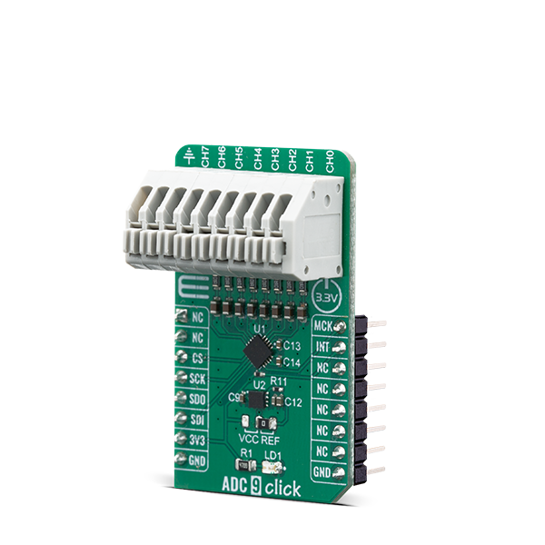
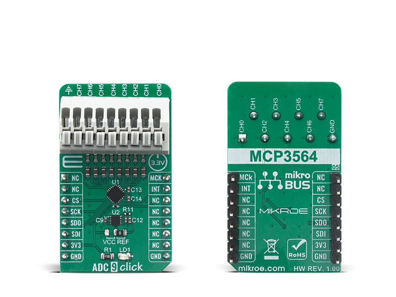
ADC 9 Click is based on MCP3564 a 24-bit Delta-Sigma Analog-to-Digital Converter with programmable data rate of up to 153.6 ksps from Microchip. It offer integrated features, such as internal oscillator, temperature sensor and burnout sensor detection, in order to reduce system component count and total solution cost.
Do you want to subscribe in order to receive notifications regarding "ADC 9 click" changes.
Do you want to unsubscribe in order to stop receiving notifications regarding "ADC 9 click" changes.
Do you want to report abuse regarding "ADC 9 click".


Library Description
The library covers necessary functions that enables the usage of the ADC 9 click board. User can read and write data of variable lenght and read and calculate ADC values.
Key functions:
uint8_t adc9_write_fast_cmd ( uint8_t dev_adr, uint8_t cmd ); - Function is used to execute fast command.uint8_t adc9_read_def_adc ( uint8_t dev_adr, int32_t *rd_data ); - Function is used to read ADC value when the default fata format is applied.float adc9_volt_calc ( int32_t adc_val, uint16_t v_ref, uint8_t gain ); - Function is used to calculate voltage based on ADC values.Examples description
The application is composed of three sections :
void application_task ( )
{
    mikrobus_logWrite( "Setup... ", _LOG_LINE );
    adc9_meas_init( );
    mikrobus_logWrite( "Done! ", _LOG_LINE );

    while ( adc9_irq_pin_state( ) )
    {
    }
    adc9_read_def_adc ( ADC9_DEVICE_ADR, &adc_value );

    LongToStr( adc_value, log_txt );
    mikrobus_logWrite( "ADC Value : ", _LOG_TEXT );
    Ltrim( log_txt );
    mikrobus_logWrite( log_txt, _LOG_LINE );

    m_volts = adc9_volt_calc ( adc_value, v_ref, 1 );
    FloatToStr( m_volts, log_txt );
    mikrobus_logWrite( "Voltage in milivolts : ", _LOG_TEXT );
    Ltrim( log_txt );
    mikrobus_logWrite( log_txt, _LOG_TEXT );
    mikrobus_logWrite( "mV", _LOG_LINE );

    mikrobus_logWrite( "------------------------", _LOG_LINE );
    Delay_ms( 1000 );
}
void adc9_meas_init ( ); Function is used to easily apply desired settings.The full application code, and ready to use projects can be found on our LibStock page.
Other mikroE Libraries used in the example:
Additional notes and informations
Depending on the development board you are using, you may need USB UART click, USB UART 2 click or RS232 click to connect to your PC, for development systems with no UART to USB interface available on the board. The terminal available in all MikroElektronika compilers, or any other terminal application of your choice, can be used to read the message.Library Description
The library covers necessary functions that enables the usage of the ADC 9 click board. User can read and write data of variable lenght and read and calculate ADC values.
Key functions:
uint8_t adc9_write_fast_cmd ( uint8_t dev_adr, uint8_t cmd ); - Function is used to execute fast command.uint8_t adc9_read_def_adc ( uint8_t dev_adr, int32_t *rd_data ); - Function is used to read ADC value when the default fata format is applied.float adc9_volt_calc ( int32_t adc_val, uint16_t v_ref, uint8_t gain ); - Function is used to calculate voltage based on ADC values.Examples description
The application is composed of three sections :
void application_task ( )
{
    mikrobus_logWrite( "Setup... ", _LOG_LINE );
    adc9_meas_init( );
    mikrobus_logWrite( "Done! ", _LOG_LINE );

    while ( adc9_irq_pin_state( ) )
    {
    }
    adc9_read_def_adc ( ADC9_DEVICE_ADR, &adc_value );

    LongToStr( adc_value, log_txt );
    mikrobus_logWrite( "ADC Value : ", _LOG_TEXT );
    Ltrim( log_txt );
    mikrobus_logWrite( log_txt, _LOG_LINE );

    m_volts = adc9_volt_calc ( adc_value, v_ref, 1 );
    FloatToStr( m_volts, log_txt );
    mikrobus_logWrite( "Voltage in milivolts : ", _LOG_TEXT );
    Ltrim( log_txt );
    mikrobus_logWrite( log_txt, _LOG_TEXT );
    mikrobus_logWrite( "mV", _LOG_LINE );

    mikrobus_logWrite( "------------------------", _LOG_LINE );
    Delay_ms( 1000 );
}
void adc9_meas_init ( ); Function is used to easily apply desired settings.Other mikroE Libraries used in the example:
Additional notes and informations
Depending on the development board you are using, you may need USB UART click, USB UART 2 click or RS232 click to connect to your PC, for development systems with no UART to USB interface available on the board. The terminal available in all MikroElektronika compilers, or any other terminal application of your choice, can be used to read the message.


