TOP Contributors

  1. MIKROE (2779 codes)
  2. Alcides Ramos (376 codes)
  3. Shawon Shahryiar (307 codes)
  4. jm_palomino (118 codes)
  5. Bugz Bensce (97 codes)
  6. S P (73 codes)
  7. dany (71 codes)
  8. MikroBUS.NET Team (35 codes)
  9. NART SCHINACKOW (34 codes)
  10. Armstrong Subero (27 codes)

Most Downloaded

  1. Timer Calculator (139566 times)
  2. FAT32 Library (72041 times)
  3. Network Ethernet Library (57256 times)
  4. USB Device Library (47615 times)
  5. Network WiFi Library (43219 times)
  6. FT800 Library (42566 times)
  7. GSM click (29930 times)
  8. mikroSDK (28292 times)
  9. PID Library (26933 times)
  10. microSD click (26309 times)
Libstock prefers package manager

Package Manager

We strongly encourage users to use Package manager for sharing their code on Libstock website, because it boosts your efficiency and leaves the end user with no room for error. [more info]

< Back
mikroSDK Library

POWER MUX click

Rating:

5

Author: MIKROE

Last Updated: 2021-01-29

Package Version: 1.0.0.0

mikroSDK Library: 1.0.0.0

Category: Power Switch

Downloaded: 2112 times

Not followed.

License: MIT license  

Power MUX Click features power multiplexer that enables transition between two power supplies (such as a battery and a wall adapter), each operating at 2.8V to 5.5V and delivering up to 2A current depending on the package.

No Abuse Reported

Do you want to subscribe in order to receive notifications regarding "POWER MUX click" changes.

Do you want to unsubscribe in order to stop receiving notifications regarding "POWER MUX click" changes.

Do you want to report abuse regarding "POWER MUX click".
  • mikroSDK Library 2.0.0.0
  • Comments (0)
DOWNLOAD LINK RELATED COMPILER CONTAINS
mikroBasic PRO for ARM
  • lib
  • src
  • exa
  • hlp
  • hex
  • sch
  • pcb
  • doc
mikroBasic PRO for AVR
  • lib
  • src
  • exa
  • hlp
  • hex
  • sch
  • pcb
  • doc
mikroBasic PRO for dsPIC30/33 & PIC24
  • lib
  • src
  • exa
  • hlp
  • hex
  • sch
  • pcb
  • doc
mikroBasic PRO for FT90x
  • lib
  • src
  • exa
  • hlp
  • hex
  • sch
  • pcb
  • doc
mikroBasic PRO for PIC
  • lib
  • src
  • exa
  • hlp
  • hex
  • sch
  • pcb
  • doc
mikroBasic PRO for PIC32
  • lib
  • src
  • exa
  • hlp
  • hex
  • sch
  • pcb
  • doc
mikroC PRO for ARM
  • lib
  • src
  • exa
  • hlp
  • hex
  • sch
  • pcb
  • doc
mikroC PRO for AVR
  • lib
  • src
  • exa
  • hlp
  • hex
  • sch
  • pcb
  • doc
mikroC PRO for dsPIC30/33 & PIC24
  • lib
  • src
  • exa
  • hlp
  • hex
  • sch
  • pcb
  • doc
mikroC PRO for FT90x
  • lib
  • src
  • exa
  • hlp
  • hex
  • sch
  • pcb
  • doc
mikroC PRO for PIC
  • lib
  • src
  • exa
  • hlp
  • hex
  • sch
  • pcb
  • doc
mikroC PRO for PIC32
  • lib
  • src
  • exa
  • hlp
  • hex
  • sch
  • pcb
  • doc
mikroPascal PRO for ARM
  • lib
  • src
  • exa
  • hlp
  • hex
  • sch
  • pcb
  • doc
mikroPascal PRO for AVR
  • lib
  • src
  • exa
  • hlp
  • hex
  • sch
  • pcb
  • doc
mikroPascal PRO for dsPIC30/33 & PIC24
  • lib
  • src
  • exa
  • hlp
  • hex
  • sch
  • pcb
  • doc
mikroPascal PRO for FT90x
  • lib
  • src
  • exa
  • hlp
  • hex
  • sch
  • pcb
  • doc
mikroPascal PRO for PIC
  • lib
  • src
  • exa
  • hlp
  • hex
  • sch
  • pcb
  • doc
mikroPascal PRO for PIC32
  • lib
  • src
  • exa
  • hlp
  • hex
  • sch
  • pcb
  • doc

mikroSDK Library Blog

Power MUX Click

Power MUX Click

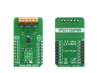
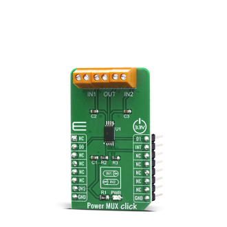
Native view of the Power MUX Click board.

View full image
Power MUX Click

Power MUX Click

Front and back view of the Power MUX Click board.

View full image

Library Description

The library covers all the necessary functions to control POWER MUX click board. POWER MUX click communicates with the target board through the RST, PWM and INT line. This library offers functions for setting D0 and D1 pins or to use predefined output from input channel 1, output from input channel 2, automatic output channel selection and disable output settings.

Key functions:

  • void powermux_output_input_ch_1 ( ); - Function is used to set output from input channel 1.
  • void powermux_output_input_ch_2 ( ); - Function is used to set output from input channel 2.
  • void powermux_auto_sel_input_ch ( ); - Function is used to set automatic output channel selection.

Examples description

The application is composed of three sections :

  • System Initialization - Initializes GPIO and LOG structures, sets RST and PWM pins as input as output and INT pin as input.
  • Application Initialization - Enables GPIO and starts write log.
  • Application Task - (code snippet) This example demonstrates the use of POWER MUX click board by disabling output tor 2 seconds, then enabling output from channel 1 for 5 seconds then disabling output for 2 seconds again, and repeating for output from channel 2.
void application_task ( )
{
    mikrobus_logWrite( "No output", _LOG_LINE );
    powermux_no_output( );
    Delay_ms( 2000 );
    mikrobus_logWrite( "Output from input channel 1", _LOG_LINE );
    powermux_output_input_ch_1( );
    Delay_ms( 5000 );
    mikrobus_logWrite( "No output", _LOG_LINE );
    powermux_no_output( );
    Delay_ms( 2000 );
    mikrobus_logWrite( "Output from input channel 2", _LOG_LINE );
    powermux_output_input_ch_2( );
    Delay_ms( 5000 );
    mikrobus_logWrite( "No output", _LOG_LINE );
    powermux_no_output( );
    Delay_ms( 2000 );
    mikrobus_logWrite( "auto select output channel", _LOG_LINE );
    powermux_auto_sel_input_ch( );
    Delay_ms( 5000 );
}


Other mikroE Libraries used in the example:

  • UART

Additional notes and informations

Depending on the development board you are using, you may need USB UART clickUSB UART 2 click or RS232 click to connect to your PC, for development systems with no UART to USB interface available on the board. The terminal available in all MikroElektronika compilers, or any other terminal application of your choice, can be used to read the message.

ALSO FROM THIS AUTHOR

DC Motor 4 click

0

DC MOTOR 4 click is capable of driving motors between 4.5V and 36V. It carries the MAX14870 motor driver from Maxim Integrated. The click is designed to run on either 3.3V or 5V power supply. DC MOTOR 4 click communicates with the target MCU over the following pins on the mikroBUSâ„¢ line: PWM, AN, CS, and INT.

[Learn More]

Programmable Relay Timers (AVR)

11

Build your own programmable timer relays using AVR-Ready1, Keypad 4x4 board with EasyPull, RTC, Relay 4 and LCD 2x16 character display with adapter. Just load the demonstration project code and your device is ready to control 4 separate relays.

[Learn More]

LightRanger 3 click

5

Light Ranger 3 click is an accurate distance measurement Click board based on a ToF (Time of Flight) measurement principle.

[Learn More]