TOP Contributors

  1. MIKROE (2650 codes)
  2. Alcides Ramos (350 codes)
  3. Shawon Shahryiar (307 codes)
  4. jm_palomino (112 codes)
  5. Chisanga Mumba (90 codes)
  6. S P (73 codes)
  7. dany (71 codes)
  8. MikroBUS.NET Team (35 codes)
  9. NART SCHINACKOW (34 codes)
  10. Armstrong Subero (27 codes)

Most Downloaded

  1. Timer Calculator (136554 times)
  2. FAT32 Library (69757 times)
  3. Network Ethernet Library (55855 times)
  4. USB Device Library (46195 times)
  5. Network WiFi Library (41817 times)
  6. FT800 Library (41010 times)
  7. GSM click (28931 times)
  8. PID Library (26386 times)
  9. mikroSDK (26297 times)
  10. microSD click (25305 times)
Libstock prefers package manager

Package Manager

We strongly encourage users to use Package manager for sharing their code on Libstock website, because it boosts your efficiency and leaves the end user with no room for error. [more info]

< Back
mikroSDK Library

Flash click

Rating:

0

Author: MIKROE

Last Updated: 2018-06-01

Package Version: 1.0.0.1

mikroSDK Library: 1.0.0.0

Category: FLASH

Downloaded: 9437 times

Followed by: 2 users

License: MIT license  

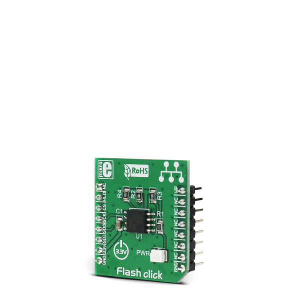
The Flash memory module used on this Click board is the EN25Q80B, an 8 Mbit serial Flash memory with 4 KB Uniform Sector, from EON Silicon Solutions. The Flash memory density is usually expressed in bits, so exactly 8,388,608 bits are organized in units (or words, also known as bytes) of 8 bits, which gives 1,048,576 bytes of data memory.

No Abuse Reported

Do you want to subscribe in order to receive notifications regarding "Flash click" changes.

Do you want to unsubscribe in order to stop receiving notifications regarding "Flash click" changes.

Do you want to report abuse regarding "Flash click".

  • mikroSDK Library 2.0.0.0
  • Comments (0)
DOWNLOAD LINK RELATED COMPILER CONTAINS
mikroBasic PRO for ARM
  • lib
  • src
  • exa
  • hlp
  • hex
  • sch
  • pcb
  • doc
mikroBasic PRO for AVR
  • lib
  • src
  • exa
  • hlp
  • hex
  • sch
  • pcb
  • doc
mikroBasic PRO for dsPIC30/33 & PIC24
  • lib
  • src
  • exa
  • hlp
  • hex
  • sch
  • pcb
  • doc
mikroBasic PRO for FT90x
  • lib
  • src
  • exa
  • hlp
  • hex
  • sch
  • pcb
  • doc
mikroBasic PRO for PIC
  • lib
  • src
  • exa
  • hlp
  • hex
  • sch
  • pcb
  • doc
mikroBasic PRO for PIC32
  • lib
  • src
  • exa
  • hlp
  • hex
  • sch
  • pcb
  • doc
mikroC PRO for ARM
  • lib
  • src
  • exa
  • hlp
  • hex
  • sch
  • pcb
  • doc
mikroC PRO for AVR
  • lib
  • src
  • exa
  • hlp
  • hex
  • sch
  • pcb
  • doc
mikroC PRO for dsPIC30/33 & PIC24
  • lib
  • src
  • exa
  • hlp
  • hex
  • sch
  • pcb
  • doc
mikroC PRO for FT90x
  • lib
  • src
  • exa
  • hlp
  • hex
  • sch
  • pcb
  • doc
mikroC PRO for PIC
  • lib
  • src
  • exa
  • hlp
  • hex
  • sch
  • pcb
  • doc
mikroC PRO for PIC32
  • lib
  • src
  • exa
  • hlp
  • hex
  • sch
  • pcb
  • doc
mikroPascal PRO for ARM
  • lib
  • src
  • exa
  • hlp
  • hex
  • sch
  • pcb
  • doc
mikroPascal PRO for AVR
  • lib
  • src
  • exa
  • hlp
  • hex
  • sch
  • pcb
  • doc
mikroPascal PRO for dsPIC30/33 & PIC24
  • lib
  • src
  • exa
  • hlp
  • hex
  • sch
  • pcb
  • doc
mikroPascal PRO for FT90x
  • lib
  • src
  • exa
  • hlp
  • hex
  • sch
  • pcb
  • doc
mikroPascal PRO for PIC
  • lib
  • src
  • exa
  • hlp
  • hex
  • sch
  • pcb
  • doc
mikroPascal PRO for PIC32
  • lib
  • src
  • exa
  • hlp
  • hex
  • sch
  • pcb
  • doc

mikroSDK Library Blog

Flash click

Flash click

Native view of the Flash click board.

View full image
Flash click

Flash click

Front and back view of the Flash click board.

View full image

Key functions:

  • uint8_t flash_WriteArray(uint32_t address, uint8_t* pData, uint16_t nCount); - The function writes data to successive addresses.
  • void flash_ReadArray(uint32_t address, uint8_t* pData, uint16_t nCount) - The function reads the data to successive addresses. 

Examples Description

The application is composed of three sections:

  • System Initialization - CS GPIO and SPI module initialization.
  • Application Initialization - Flash click driver and click initialization.
  • Application Task - (code snippet) - Writing data to click memory and displaying the read data via UART.
void applicationTask()
{
 flash_SectorErase(0x015015);
 mikrobus_logWrite("Writing MikroE to Flash memory, from address 0x015015:"
,_LOG_LINE);
 flash_WriteArray (0x015015, &wrData[0], 9);
 mikrobus_logWrite("Reading 9 bytes of Flash memory, from address 0x015015:"
,_LOG_LINE);
 flash_ReadArray (0x015015,&rdData[0],9);
 mikrobus_logWrite("Data read: ",_LOG_TEXT);
 mikrobus_logWrite(rdData,_LOG_LINE);
 Delay_ms(1000);
}

Other mikroE Libraries used in the example:

  • SPI
  • UART

Additional notes and information Depending on the development board you are using, you may need USB UART clickUSB UART 2 click or RS232 click to connect to your PC, for development systems with no UART to USB interface available on the board. The terminal available in all MikroElektronika compilers, or any other terminal application of your choice, can be used to read the message.


ALSO FROM THIS AUTHOR

Led Driver 8 click

5

LED Driver 8 Click is a compact add-on board optimized for dimming and blinking 32 mA RGBA LEDs. This board features the PCA9957HNMP, 24-channel SPI-compatible constant current LED driver from NXP Semiconductors.

[Learn More]

mikromedia for STM32 M3 - Examples

0

Set of examples for mikromedia for STM32 M3. Provided examples demonstrate working with mikromedia's various features and modules: - Accelerometer - MMC SD card - MP3 - Serial Flash - TFT - Touch Panel - USB UART

[Learn More]

ECG 7 click

0

ECG 7 Click is a compact add-on board that records the heart's electrical activity. This board features the MCP6N16, a single zero-drift instrumentation amplifier with selectable gain from Microchip. In addition to the jack connector provided for connecting the cable with ECG electrodes, this Click boardâ„¢ offers the possibility of connecting electrodes through screw terminals or an onboard header if the electrode connection does not match the jack connector. Besides, the user is allowed to process the output signal in analog or digital form.

[Learn More]