TOP Contributors

  1. MIKROE (2784 codes)
  2. Alcides Ramos (405 codes)
  3. Shawon Shahryiar (307 codes)
  4. jm_palomino (133 codes)
  5. Bugz Bensce (97 codes)
  6. S P (73 codes)
  7. dany (71 codes)
  8. MikroBUS.NET Team (35 codes)
  9. NART SCHINACKOW (34 codes)
  10. Armstrong Subero (27 codes)

Most Downloaded

  1. Timer Calculator (141305 times)
  2. FAT32 Library (74107 times)
  3. Network Ethernet Library (58718 times)
  4. USB Device Library (48831 times)
  5. Network WiFi Library (44526 times)
  6. FT800 Library (44078 times)
  7. GSM click (30834 times)
  8. mikroSDK (29673 times)
  9. PID Library (27357 times)
  10. microSD click (27252 times)
Libstock prefers package manager

Package Manager

We strongly encourage users to use Package manager for sharing their code on Libstock website, because it boosts your efficiency and leaves the end user with no room for error. [more info]

< Back
mikroSDK Library

eFuse 2 click

Rating:

5

Author: MIKROE

Last Updated: 2021-01-29

Package Version: 1.0.0.0

mikroSDK Library: 1.0.0.0

Category: Power Switch

Downloaded: 2586 times

Not followed.

License: MIT license  

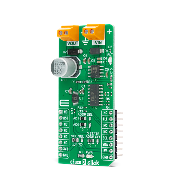
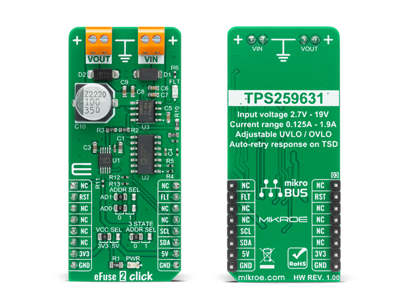
eFuse 2 Click is a compact add-on board that contains an integrated FET hot-swap device. This board features the TPS259631, a highly integrated circuit protection and power management solution from Texas Instruments.

No Abuse Reported

Do you want to subscribe in order to receive notifications regarding "eFuse 2 click" changes.

Do you want to unsubscribe in order to stop receiving notifications regarding "eFuse 2 click" changes.

Do you want to report abuse regarding "eFuse 2 click".

  • mikroSDK Library 2.0.0.0
  • Comments (0)
DOWNLOAD LINK RELATED COMPILER CONTAINS
mikroBasic PRO for ARM
  • lib
  • src
  • exa
  • hlp
  • hex
  • sch
  • pcb
  • doc
mikroBasic PRO for AVR
  • lib
  • src
  • exa
  • hlp
  • hex
  • sch
  • pcb
  • doc
mikroBasic PRO for dsPIC30/33 & PIC24
  • lib
  • src
  • exa
  • hlp
  • hex
  • sch
  • pcb
  • doc
mikroBasic PRO for FT90x
  • lib
  • src
  • exa
  • hlp
  • hex
  • sch
  • pcb
  • doc
mikroBasic PRO for PIC
  • lib
  • src
  • exa
  • hlp
  • hex
  • sch
  • pcb
  • doc
mikroBasic PRO for PIC32
  • lib
  • src
  • exa
  • hlp
  • hex
  • sch
  • pcb
  • doc
mikroC PRO for ARM
  • lib
  • src
  • exa
  • hlp
  • hex
  • sch
  • pcb
  • doc
mikroC PRO for AVR
  • lib
  • src
  • exa
  • hlp
  • hex
  • sch
  • pcb
  • doc
mikroC PRO for dsPIC30/33 & PIC24
  • lib
  • src
  • exa
  • hlp
  • hex
  • sch
  • pcb
  • doc
mikroC PRO for FT90x
  • lib
  • src
  • exa
  • hlp
  • hex
  • sch
  • pcb
  • doc
mikroC PRO for PIC
  • lib
  • src
  • exa
  • hlp
  • hex
  • sch
  • pcb
  • doc
mikroC PRO for PIC32
  • lib
  • src
  • exa
  • hlp
  • hex
  • sch
  • pcb
  • doc
mikroPascal PRO for ARM
  • lib
  • src
  • exa
  • hlp
  • hex
  • sch
  • pcb
  • doc
mikroPascal PRO for AVR
  • lib
  • src
  • exa
  • hlp
  • hex
  • sch
  • pcb
  • doc
mikroPascal PRO for dsPIC30/33 & PIC24
  • lib
  • src
  • exa
  • hlp
  • hex
  • sch
  • pcb
  • doc
mikroPascal PRO for FT90x
  • lib
  • src
  • exa
  • hlp
  • hex
  • sch
  • pcb
  • doc
mikroPascal PRO for PIC
  • lib
  • src
  • exa
  • hlp
  • hex
  • sch
  • pcb
  • doc
mikroPascal PRO for PIC32
  • lib
  • src
  • exa
  • hlp
  • hex
  • sch
  • pcb
  • doc

mikroSDK Library Blog

eFuse 2 Click

eFuse 2 Click

Native view of the eFuse 2 Click board.

View full image
eFuse 2 Click

eFuse 2 Click

Front and back view of the eFuse 2 Click board.

View full image

Library Description

The library covers all the necessary functions to control eFuse 2 Click board™. Library performs a standard I2C interface communication.

Key functions:

  • float *min_voltage, float *max_voltage ) - Set operating voltage function.
  • void efuse2_set_operating_current ( float current ) - Set operating current function.
  • void efuse2_operating_mode ( uint8_t mode ) - Set operating mode function.

Examples description

The application is composed of three sections :

  • System Initialization - Initializes I2C, set RST pin as an output, set INT pin as input and start to write log.
  • Application Initialization - Initialization driver enables - I2C, AD5175: enable write, set the normal operating mode and operating current to the 1,2 A; AD5241: set operating voltage to the 12,0 V; display diagnostic states and temperature.
  • Application Task - (code snippet) This is an example that demonstrate the use of the eFuse 2 Click board™. eFuse 2 Click board™ uses USB UART log to display operating voltage, OVLO, UVLO and current limit condition. This firmware provides the functions to set the operating voltage and current limiting conditions in order to provide the threshold of the fault conditions. When one of the fault conditions is met, the microcontroller is notified via INT pin which is checked by the app to initiate a shutdown mode. All data logs write on USB UART changes every 2000 milliseconds.
void application_task ( )
{
    if ( efuse2_get_fault( ) == EFUSE2_FAULT )
    {
        efuse2_operating_mode( EFUSE2_AD5175_SHUTDOWN_MODE );
        Delay_ms( 1000 );

        mikrobus_logWrite( "        Shutdown Mode        ", _LOG_LINE );
        mikrobus_logWrite( "-----------------------------", _LOG_LINE );
        for ( ; ; );
    }

    FloatToStr( op_voltage, log_text );
    mikrobus_logWrite( " Oper. Voltage : ", _LOG_TEXT );
    mikrobus_logWrite( log_text, _LOG_TEXT );
    mikrobus_logWrite( " V", _LOG_LINE );

    FloatToStr( min_voltage, log_text );
    mikrobus_logWrite( " Undervoltage  : ", _LOG_TEXT );
    mikrobus_logWrite( log_text, _LOG_TEXT );
    mikrobus_logWrite( " V", _LOG_LINE );

    FloatToStr( max_voltage, log_text );
    mikrobus_logWrite( " Overvoltage   : ", _LOG_TEXT );
    mikrobus_logWrite( log_text, _LOG_TEXT );
    mikrobus_logWrite( " V", _LOG_LINE );

    FloatToStr( op_current, log_text );
    mikrobus_logWrite( " Current Limit : ", _LOG_TEXT );
    mikrobus_logWrite( log_text, _LOG_TEXT );
    mikrobus_logWrite( " A", _LOG_LINE );
    mikrobus_logWrite( "-----------------------------", _LOG_LINE );
    Delay_ms( 2000 );
}

Other mikroE Libraries used in the example:

  • I2C
  • UART
  • Conversions

Additional notes and informations

Depending on the development board you are using, you may need USB UART clickUSB UART 2 click or RS232 click to connect to your PC, for development systems with no UART to USB interface available on the board. The terminal available in all MikroElektronika compilers, or any other terminal application of your choice, can be used to read the message.

ALSO FROM THIS AUTHOR

DIGI IN 2 Click

0

DIGI IN 2 Click is a compact add-on board designed for converting high-voltage industrial signals into logic-level outputs, ideal for enhancing industrial control systems. This board features the MAX22196, a high-performance octal industrial sink/source digital input IC from Analog Devices. This Click board™ stands out for its ability to interface eight industrial inputs (8V-24V) via SPI, configurable as either sinking or sourcing with built-in current limiters, ensuring adherence to IEC 61131-2 standards.

[Learn More]

LCD Mono click

5

LCD Mono Click is a Click boardâ„¢ that uses the LS013B7DH03 LCD display from Sharp which combined with the EFM32, from Silicon Labs, and its energy saving capabilities creates a powerful display application.

[Learn More]

LDC Touch Click

0

LDC Touch Click is a compact add-on board optimized for inductive touch applications. This board features the LDC3114-Q1, a four-channel inductance-to-digital converter for low-power proximity and touch-button sensing from Texas Instruments. It comes with an adjustable sensitivity per input channel and operational power mode selection and measures frequency shifts caused by micro-deflection in the conductive targets formed by button presses. These presses are reported through a compatible I2C interface beside four LED indicators for its visual indication. This Click board™ enables touch button design for human-machine interface and precise linear position sensing of metal targets for automotive, consumer, and industrial applications by allowing access to the raw data representing the inductance value.

[Learn More]