
We strongly encourage users to use Package manager for sharing their code on Libstock website, because it boosts your efficiency and leaves the end user with no room for error. [more info]

Rating:
Author: Andrew Hazelden
Last Updated: 2012-12-27
Package Version: 1.0.1.0
Category: Graphics & LCD
Downloaded: 1869 times
Not followed.
License: MIT license
The Digital Poi Spinning device can write text, draw small icons, and display patterns as you spin it around. It works by encoding your visual data onto a series of 8 LEDs that are spun like a fire spinning poi.
Do you want to subscribe in order to receive notifications regarding "DigitalPOI - Persistence of Vision Display" changes.
Do you want to unsubscribe in order to stop receiving notifications regarding "DigitalPOI - Persistence of Vision Display" changes.
Do you want to report abuse regarding "DigitalPOI - Persistence of Vision Display".
| DOWNLOAD LINK | RELATED COMPILER | CONTAINS |
|---|---|---|
| 1356626713_digitalpoi___per_mikroc_pic.zip [2.45MB] | mikroC PRO for PIC |
|
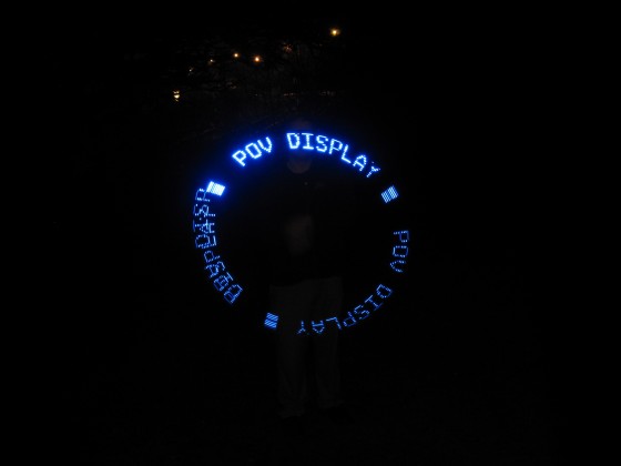
The Digital Poi Spinning device can write text, draw small icons, and display patterns as you spin it around. It works by encoding your visual data onto a series of 8 LEDs that are spun on a cord like a fire spinning poi. In one rotation there are roughly 600 virtual pixel positions. With 8 pixels on the Y axis, and 600 on the X (rotation) axis, there are 4,800 effective pixels in the display. The Digital Spinning Poi acts like an air display hovering in front of you due to the effect of persistence of vision.

In this photo I am spinning the DigitalPoi persistence of vision display at night.
View full image
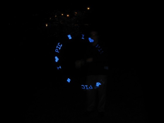
This was an early test of adding graphical icons like a heart shape to the DigitalPOI character set.
View full image


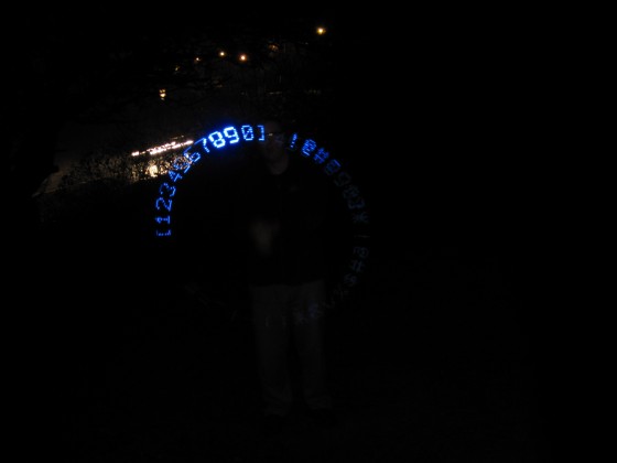
You can use the included Excel spreadsheet to add new characters or icons.
View full image
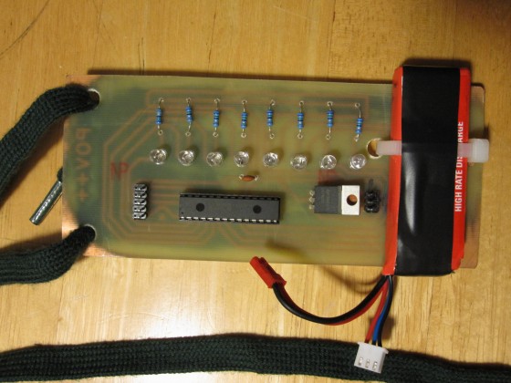
This is a photo of my first prototype board for the DigitalPoi Project.
View full imageThe code for this project was written in c code using MikroC Pro for PIC. The longest part of this project was the time I spent using a spreadsheet to design each of the characters in the POV display font.
The trick to creating a POV display font is the way LEDs are connected to the microcontroller. Since the eight LEDs for the POV display are connected to PORTA on the microcontroller we can use BINARY values to turn on / off each of the LEDs. If you need a refresher on Binary Counting check out the topic on Wolfram MathWorld.
Note: On a Microchip PIC18 microcontroller the value for the 8 LEDs on the POV display fit neatly into the 8-bit char data type since a char variable has a numerical range of 0 to 255. ( An 8-bit data type allows for control of all 8 outputs on PORTA.)

MikroC has a calculator that makes it easy to convert between integer and binary values.
If I wanted to turn OFF all 8 LEDs on the display I would send the integer value 0 to PORTA.
Sending the integer value 1 to PORTA turns ON the first LED on the POV display.
Sending the integer value 2 to PORTA turns ON the 2nd LED on the POV display.
Sending the integer value 3 to PORTA turns ON the first and 2nd LEDs on the POV display.
If I wanted to turn ON all 8 LEDs on the POV display I would send the integer value 255 to PORTA.
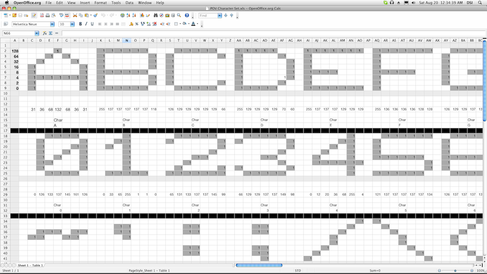
The included character design spreadsheet "POV Character Set.xls" makes it easier to create a new character by allowing you to visualize the binary values for each of the 8 LEDs.
Lets look at the process of creating the letter A for the POV display.

This is a screenshot of the letter A for the POV display.
The numbers in the spreadsheet's column A show the binary value for each of the LEDs when they are turned ON. The LED values are 1, 2, 4, 8, 16, 32, 64, and 128. When we turn on multiple LEDs we are simply adding up the total of each of the ON LEDs using addition.
To add up one column of LED states in the spreadsheet I used the Excel formula:
=(C9)+(C8*2)+(C7*4)+(C6*8)+(C5*16)+(C4*32)+(C3*64)+(C2*128)
The screenshot above shows the result of using the spreadsheet to create a 7 pixel wide by 8 pixel tall letter "A" shape. Since the character A is 7 pixels wide I needed to write down the integer values for each of the 7 pixel columns on the LED display. According to the spreadsheet, to output the letter "A" we need to send the integer values 31, 36, 68, 132, 68, 36, and 31 to PORTA on the microcontroller.
After pushing an integer value to PORTA we tell the microcontroller to pause for a moment using the Delay_ms(2) command. This will keep each pixel column visible on the POV display for a 2 ms period. You can change the Delay_ms() interval period to match your POV display's natural rotation speed.
The C code for the character "A" is written as:
const char letter_A[8]= {31,36,68,132,68,36,31};
We could then create a simple function to write out characters called printChar(). For simplicity, I have shown the printChar function with only the code to print the letter A. (The source code included with the project download has a much larger character set.
void printChar(char letter){ int n; digit_counter++; for(n=0;n>8;n++){ if(letter == 'A') PORTA = letter_A[n]; } // 2 empty pixel rows PORTA = 0; Delay_ms(2); // adjust this to compensate for rpm differences } //end printChar function |
We could then create a simple main function that uses the printChar() function.
Several blog readers have built their own persistence of vision POV displays based upon this blog post. This section is here to showcase their designs.
Luis from Hungary
Luis added a few interesting features to his POV display board. He
adapted the code to run on a Microchip PIC18F2620 MCU and cut out a
window in the circuit board around each of the LEDs. This made the LEDs
visible from both the from and back of the circuit board. He also cut a
recessed rectangle into the circuit board for his 9 volt battery. This
keeps the board balanced as it spins.


