TOP Contributors

  1. MIKROE (2784 codes)
  2. Alcides Ramos (405 codes)
  3. Shawon Shahryiar (307 codes)
  4. jm_palomino (133 codes)
  5. Bugz Bensce (97 codes)
  6. S P (73 codes)
  7. dany (71 codes)
  8. MikroBUS.NET Team (35 codes)
  9. NART SCHINACKOW (34 codes)
  10. Armstrong Subero (27 codes)

Most Downloaded

  1. Timer Calculator (141958 times)
  2. FAT32 Library (75148 times)
  3. Network Ethernet Library (59420 times)
  4. USB Device Library (49412 times)
  5. Network WiFi Library (45227 times)
  6. FT800 Library (44813 times)
  7. GSM click (31379 times)
  8. mikroSDK (30365 times)
  9. microSD click (27741 times)
  10. PID Library (27595 times)
Libstock prefers package manager

Package Manager

We strongly encourage users to use Package manager for sharing their code on Libstock website, because it boosts your efficiency and leaves the end user with no room for error. [more info]

< Back
mikroSDK Library

BarGraph click

Rating:

0

Author: MIKROE

Last Updated: 2018-04-04

Package Version: 1.0.0.1

mikroSDK Library: 1.0.0.0

Category: LED segment

Downloaded: 9249 times

Followed by: 1 user

License: MIT license  

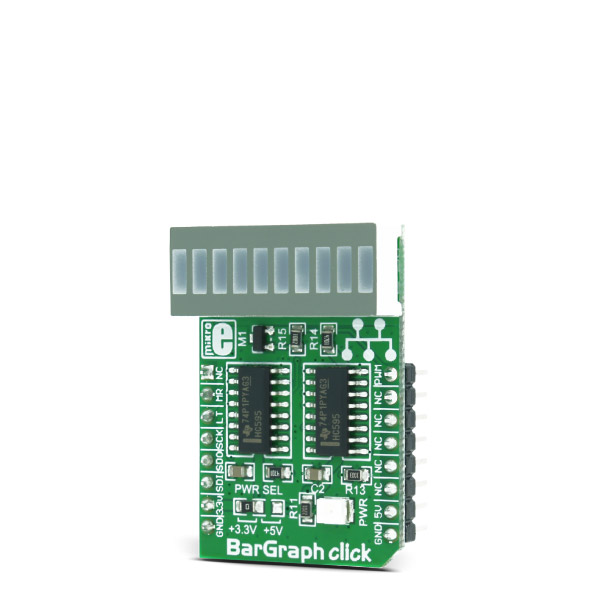
This is a demonstration example for BarGraph click.
Bar Graph is representing ADC value measured on Poetntiometer P1.
On Potentiometer P2 user can adjust PWM for LCD backlight.

No Abuse Reported

Do you want to subscribe in order to receive notifications regarding "BarGraph click" changes.

Do you want to unsubscribe in order to stop receiving notifications regarding "BarGraph click" changes.

Do you want to report abuse regarding "BarGraph click".

  • mikroSDK Library 2.0.0.0
  • Comments (0)
DOWNLOAD LINK RELATED COMPILER CONTAINS
mikroBasic PRO for ARM
  • lib
  • src
  • exa
  • hlp
  • hex
  • sch
  • pcb
  • doc
mikroBasic PRO for AVR
  • lib
  • src
  • exa
  • hlp
  • hex
  • sch
  • pcb
  • doc
mikroBasic PRO for dsPIC30/33 & PIC24
  • lib
  • src
  • exa
  • hlp
  • hex
  • sch
  • pcb
  • doc
mikroBasic PRO for FT90x
  • lib
  • src
  • exa
  • hlp
  • hex
  • sch
  • pcb
  • doc
mikroBasic PRO for PIC
  • lib
  • src
  • exa
  • hlp
  • hex
  • sch
  • pcb
  • doc
mikroBasic PRO for PIC32
  • lib
  • src
  • exa
  • hlp
  • hex
  • sch
  • pcb
  • doc
mikroC PRO for ARM
  • lib
  • src
  • exa
  • hlp
  • hex
  • sch
  • pcb
  • doc
mikroC PRO for AVR
  • lib
  • src
  • exa
  • hlp
  • hex
  • sch
  • pcb
  • doc
mikroC PRO for dsPIC30/33 & PIC24
  • lib
  • src
  • exa
  • hlp
  • hex
  • sch
  • pcb
  • doc
mikroC PRO for FT90x
  • lib
  • src
  • exa
  • hlp
  • hex
  • sch
  • pcb
  • doc
mikroC PRO for PIC
  • lib
  • src
  • exa
  • hlp
  • hex
  • sch
  • pcb
  • doc
mikroC PRO for PIC32
  • lib
  • src
  • exa
  • hlp
  • hex
  • sch
  • pcb
  • doc
mikroPascal PRO for ARM
  • lib
  • src
  • exa
  • hlp
  • hex
  • sch
  • pcb
  • doc
mikroPascal PRO for AVR
  • lib
  • src
  • exa
  • hlp
  • hex
  • sch
  • pcb
  • doc
mikroPascal PRO for dsPIC30/33 & PIC24
  • lib
  • src
  • exa
  • hlp
  • hex
  • sch
  • pcb
  • doc
mikroPascal PRO for FT90x
  • lib
  • src
  • exa
  • hlp
  • hex
  • sch
  • pcb
  • doc
mikroPascal PRO for PIC
  • lib
  • src
  • exa
  • hlp
  • hex
  • sch
  • pcb
  • doc
mikroPascal PRO for PIC32
  • lib
  • src
  • exa
  • hlp
  • hex
  • sch
  • pcb
  • doc

mikroSDK Library Blog

BarGraph click

BarGraph click

Native view of the BarGraph click board.

View full image
BarGraph click

BarGraph click

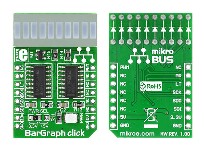
Front and back view of BarGraph click board designed in mikroBUS form factor.

View full image

Library Description

The library initializes and defines SPI bus driver and drivers that offer a choice for writing data in registers and reading data from registers. The library includes functions for logging values on the BarGraph display. A user can enable and disable the chip with the function bargraph_enable(), which is supported in the library.

Key functions:

  • void bargraph_driverInit() - Functions for initializes chip
  • void bargraph_display( uint8_t input ) - Display functions
  • void bargraph_enable( uint8_t input ) - Functions for enable the chip

Example description

The application is composed of three sections:

  • System Initialization -   Initializes SPI module and sets PWM pin, CS pin and RST pin as OUTPUT
  • Application Initialization - Initializes driver init and BarGraph init
  • Application Task - (code snippet) - Counter passes through the loop and logs the value of the counter on the bargraph display
void applicationTask()
{
 for (cnt = 0; cnt <= 10; cnt++)
 {
 bargraph_display( cnt );
 Delay_ms( 500 );
 }
}


Other MikroElektronika libraries used in the example:

  • SPI

Additional notes and information

Depending on the development board you are using, you may need USB UART clickUSB UART 2 click or RS232 click to connect to your PC, for development systems with no UART to USB interface available on the board. The terminal available in all MikroElektronika compilers, or any other terminal application of your choice, can be used to read the message.

ALSO FROM THIS AUTHOR

Rec N Play Click

0

Rec&Play Click is a digital voice recorder on a Click board™. It is based on the ISD3900, a multi-message record and playback device. It features the ChipCorder® technology, offering digital sound compression, smart message management, digitally configurable signal path, and more.

[Learn More]

NFC Tag 4 click

5

NFC Tag 4 Click is NFC RFID tag device, offering 16 Kbit of electrically erasable programmable memory (EEPROM). This Click Board offer two communication interfaces. The first one is an I2C serial link and can be operated from a DC power supply.

[Learn More]

STSPIN820 Click

0

STSPIN820 Click is a stepper motor driver with the PWM current control, selectable microstepping up to 256 microsteps, and a wide voltage range. It is based on the STSPIN820, a stepper motor driver from STSPIN8 series. Designed to be a bullet-proof solution for the new wave of demanding industrial applications, it integrates two full-bridges with low ON resistance, the control logic, and a full set of protection features, in a small 4x4mm QFN package. Its output stage implements the PWM current control with the fixed OFF time. The device can be used with the step motor voltage ranging from 7V up to 45V, and current up to 1.5A per bridge.

[Learn More]