TOP Contributors

  1. MIKROE (2784 codes)
  2. Alcides Ramos (387 codes)
  3. Shawon Shahryiar (307 codes)
  4. jm_palomino (120 codes)
  5. Bugz Bensce (97 codes)
  6. S P (73 codes)
  7. dany (71 codes)
  8. MikroBUS.NET Team (35 codes)
  9. NART SCHINACKOW (34 codes)
  10. Armstrong Subero (27 codes)

Most Downloaded

  1. Timer Calculator (140155 times)
  2. FAT32 Library (72608 times)
  3. Network Ethernet Library (57639 times)
  4. USB Device Library (47951 times)
  5. Network WiFi Library (43538 times)
  6. FT800 Library (42937 times)
  7. GSM click (30140 times)
  8. mikroSDK (28667 times)
  9. PID Library (27050 times)
  10. microSD click (26552 times)
Libstock prefers package manager

Package Manager

We strongly encourage users to use Package manager for sharing their code on Libstock website, because it boosts your efficiency and leaves the end user with no room for error. [more info]

< Back
mikroSDK Library

LPG click

Rating:

5

Author: MIKROE

Last Updated: 2019-01-29

Package Version: 1.0.0.1

mikroSDK Library: 1.0.0.0

Category: Gas

Downloaded: 5817 times

Followed by: 2 users

License: MIT license  

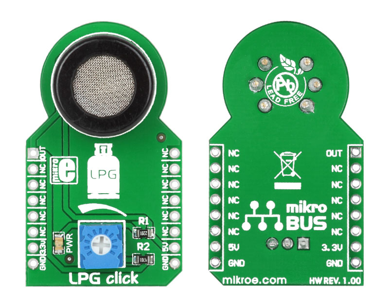
This example demonstrates usage of the LPG click board in mikroBUS form factor. LPG click is suitable for detecting LPG concentration - LPG checker. LCD shows PPM value of LPG concentration.

No Abuse Reported

Do you want to subscribe in order to receive notifications regarding "LPG click" changes.

Do you want to unsubscribe in order to stop receiving notifications regarding "LPG click" changes.

Do you want to report abuse regarding "LPG click".

  • mikroSDK Library 2.0.0.0
  • Comments (0)
DOWNLOAD LINK RELATED COMPILER CONTAINS
mikroBasic PRO for ARM
  • lib
  • src
  • exa
  • hlp
  • hex
  • sch
  • pcb
  • doc
mikroBasic PRO for AVR
  • lib
  • src
  • exa
  • hlp
  • hex
  • sch
  • pcb
  • doc
mikroBasic PRO for dsPIC30/33 & PIC24
  • lib
  • src
  • exa
  • hlp
  • hex
  • sch
  • pcb
  • doc
mikroBasic PRO for FT90x
  • lib
  • src
  • exa
  • hlp
  • hex
  • sch
  • pcb
  • doc
mikroBasic PRO for PIC
  • lib
  • src
  • exa
  • hlp
  • hex
  • sch
  • pcb
  • doc
mikroBasic PRO for PIC32
  • lib
  • src
  • exa
  • hlp
  • hex
  • sch
  • pcb
  • doc
mikroC PRO for ARM
  • lib
  • src
  • exa
  • hlp
  • hex
  • sch
  • pcb
  • doc
mikroC PRO for AVR
  • lib
  • src
  • exa
  • hlp
  • hex
  • sch
  • pcb
  • doc
mikroC PRO for dsPIC30/33 & PIC24
  • lib
  • src
  • exa
  • hlp
  • hex
  • sch
  • pcb
  • doc
mikroC PRO for FT90x
  • lib
  • src
  • exa
  • hlp
  • hex
  • sch
  • pcb
  • doc
mikroC PRO for PIC
  • lib
  • src
  • exa
  • hlp
  • hex
  • sch
  • pcb
  • doc
mikroC PRO for PIC32
  • lib
  • src
  • exa
  • hlp
  • hex
  • sch
  • pcb
  • doc
mikroPascal PRO for ARM
  • lib
  • src
  • exa
  • hlp
  • hex
  • sch
  • pcb
  • doc
mikroPascal PRO for AVR
  • lib
  • src
  • exa
  • hlp
  • hex
  • sch
  • pcb
  • doc
mikroPascal PRO for dsPIC30/33 & PIC24
  • lib
  • src
  • exa
  • hlp
  • hex
  • sch
  • pcb
  • doc
mikroPascal PRO for FT90x
  • lib
  • src
  • exa
  • hlp
  • hex
  • sch
  • pcb
  • doc
mikroPascal PRO for PIC
  • lib
  • src
  • exa
  • hlp
  • hex
  • sch
  • pcb
  • doc
mikroPascal PRO for PIC32
  • lib
  • src
  • exa
  • hlp
  • hex
  • sch
  • pcb
  • doc

mikroSDK Library Blog

LPG click board

LPG click board

Front and back side appearance of the LPG click Board.

View full image

Library Description

The library covers all the necessary functions to control LPG Click board. LPG click communicates with the target board via analog ( AN ) pin. This library contains drivers for read ADC value of MQ-5B sensor.

Key functions:

  • float lpg_voltageConversion( uint32_t adcValue, float vRef ) - Convert the voltage function.
  • float lpg_getRatio( uint32_t adcValue, float vRef ) - Get the sensor ratio function.
  • float lpg_getSensorResistance( uint32_t adcValue, float vRef ) - Get the sensor resistance.

Examples description

The application is composed of the three sections :

  • System Initialization - Initializes GPIO and LOG structures, sets AN pin as input.
  • Application Initialization - Initialization driver enables GPIO and ADC, also starts write log.
  • Application Task - (code snippet) This is a example which demonstrates the use of LGP Click board. LGP Click reads ADC value. Results are being sent to the Usart Terminal where you can track their changes. All data logs on usb uart changes for every 1 sec.
void applicationTask()
{      
    valueADC = lgp_readADC(); 
    Delay_100ms(); 
    
    IntToStr( valueADC, logText );
    mikrobus_logWrite( " ADC value: ", _LOG_TEXT );
    mikrobus_logWrite( logText, _LOG_LINE );
    mikrobus_logWrite( "-------------------", _LOG_LINE );
    Delay_1sec();
}


Additional Functions :

  • void lgp_adcInit() - Function ADC initialization.
  • uint32_t lgp_readADC() - Function read ADC value.

Other mikroE Libraries used in the example:

  • ADC
  • UART
  • Conversions

Additional notes and information

Depending on the development board you are using, you may need USB UART clickUSB UART 2 click or RS232 click to connect to your PC, for development systems with no UART to USB interface available on the board. The terminal available in all MikroElektronika compilers, or any other terminal application of your choice, can be used to read the message.

ALSO FROM THIS AUTHOR

RTC 11 click

5

RTC 11 Click is a compact add-on board that contains a real-time clock IC designed to maximize battery life and reduce overall battery requirements in wearable applications. This board features the AB0815, an ultra-low-power coupled with a highly sophisticated feature set the real-time clock from Abracon LLC.

[Learn More]

6DOF IMU 8 click

5

6DOF IMU 8 click is an advanced 6-axis motion tracking Click board, which utilizes the ISM330DLC, a high-performance System in Package (SiP), equipped with a 3-axis gyroscope, and a 3-axis accelerometer.

[Learn More]

7-SEG RGB click

0

7-SEG RGB click carries a full color single 7 segment digit display. The click is designed to run on either 3.3V or 5V power supply. It communicates with the target microcontroller over the CS, and PWM pin on the mikroBUS line.

[Learn More]