TOP Contributors

  1. MIKROE (2784 codes)
  2. Alcides Ramos (403 codes)
  3. Shawon Shahryiar (307 codes)
  4. jm_palomino (130 codes)
  5. Bugz Bensce (97 codes)
  6. S P (73 codes)
  7. dany (71 codes)
  8. MikroBUS.NET Team (35 codes)
  9. NART SCHINACKOW (34 codes)
  10. Armstrong Subero (27 codes)

Most Downloaded

  1. Timer Calculator (140921 times)
  2. FAT32 Library (73486 times)
  3. Network Ethernet Library (58270 times)
  4. USB Device Library (48472 times)
  5. Network WiFi Library (44080 times)
  6. FT800 Library (43645 times)
  7. GSM click (30522 times)
  8. mikroSDK (29254 times)
  9. PID Library (27196 times)
  10. microSD click (26922 times)
Libstock prefers package manager

Package Manager

We strongly encourage users to use Package manager for sharing their code on Libstock website, because it boosts your efficiency and leaves the end user with no room for error. [more info]

< Back
mikroSDK Library

4x4 RGB click

Rating:

1

Author: MIKROE

Last Updated: 2019-07-29

Package Version: 1.0.0.1

mikroSDK Library: 1.0.0.0

Category: LED matrix

Downloaded: 5531 times

Followed by: 2 users

License: MIT license  

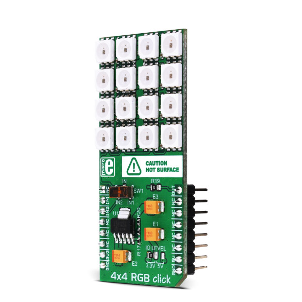
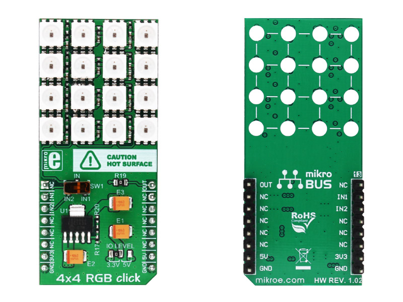
4x4 RGB click carries a matrix of 16 RGB LEDs and a MCP1826 low dropout regulator. The LED matrix is connected to the target board microcontroller through the mikroBUS RST pin. The board uses either a 3.3V or 5V power supply.

No Abuse Reported

Do you want to subscribe in order to receive notifications regarding "4x4 RGB click" changes.

Do you want to unsubscribe in order to stop receiving notifications regarding "4x4 RGB click" changes.

Do you want to report abuse regarding "4x4 RGB click".

  • mikroSDK Library 2.0.0.0
  • Comments (1)
DOWNLOAD LINK RELATED COMPILER CONTAINS
mikroBasic PRO for ARM
  • lib
  • src
  • exa
  • hlp
  • hex
  • sch
  • pcb
  • doc
mikroBasic PRO for AVR
  • lib
  • src
  • exa
  • hlp
  • hex
  • sch
  • pcb
  • doc
mikroBasic PRO for dsPIC30/33 & PIC24
  • lib
  • src
  • exa
  • hlp
  • hex
  • sch
  • pcb
  • doc
mikroBasic PRO for FT90x
  • lib
  • src
  • exa
  • hlp
  • hex
  • sch
  • pcb
  • doc
mikroBasic PRO for PIC
  • lib
  • src
  • exa
  • hlp
  • hex
  • sch
  • pcb
  • doc
mikroBasic PRO for PIC32
  • lib
  • src
  • exa
  • hlp
  • hex
  • sch
  • pcb
  • doc
mikroC PRO for ARM
  • lib
  • src
  • exa
  • hlp
  • hex
  • sch
  • pcb
  • doc
mikroC PRO for AVR
  • lib
  • src
  • exa
  • hlp
  • hex
  • sch
  • pcb
  • doc
mikroC PRO for dsPIC30/33 & PIC24
  • lib
  • src
  • exa
  • hlp
  • hex
  • sch
  • pcb
  • doc
mikroC PRO for FT90x
  • lib
  • src
  • exa
  • hlp
  • hex
  • sch
  • pcb
  • doc
mikroC PRO for PIC
  • lib
  • src
  • exa
  • hlp
  • hex
  • sch
  • pcb
  • doc
mikroC PRO for PIC32
  • lib
  • src
  • exa
  • hlp
  • hex
  • sch
  • pcb
  • doc
mikroPascal PRO for ARM
  • lib
  • src
  • exa
  • hlp
  • hex
  • sch
  • pcb
  • doc
mikroPascal PRO for AVR
  • lib
  • src
  • exa
  • hlp
  • hex
  • sch
  • pcb
  • doc
mikroPascal PRO for dsPIC30/33 & PIC24
  • lib
  • src
  • exa
  • hlp
  • hex
  • sch
  • pcb
  • doc
mikroPascal PRO for FT90x
  • lib
  • src
  • exa
  • hlp
  • hex
  • sch
  • pcb
  • doc
mikroPascal PRO for PIC
  • lib
  • src
  • exa
  • hlp
  • hex
  • sch
  • pcb
  • doc
mikroPascal PRO for PIC32
  • lib
  • src
  • exa
  • hlp
  • hex
  • sch
  • pcb
  • doc

mikroSDK Library Blog

4x4 RGB click

4x4 RGB click

Native view of the 4x4 RGB click board.

View full image
4x4 RGB click

4x4 RGB click

Front and back view of the 4x4 RGB click board.

View full image

Library Description

The library covers all the necessary functions to control 4x4 RGB click board.

Key functions:

  • void c4x4rgb_gpioDriverInit(T_PS2_P gpioObj) - Function initializes GPIO driver for the desired MIKROBUS1.

Examples description

The application is composed of the three sections :

  • System Initialization - Initializes GPIO, LOG structures.
  • Application Initialization - Initialization driver enables - GPIO.
  • Application Task - This is an example which demonstrates the use of 4x4 RGB Click board. This simple example shows all ten numbers in different colors on 4x4 RGB click. The 4x4 RGB click carries a matrix of 16 RGB LEDs and an MCP1826 low dropout regulator. These LEDs actually consist of three single-colored LEDs ( Red, Green and Blue ) in a single package. Various colors can be reproduced by mixing the intensity of each LED.
void applicationTask()
{
    mikrobus_logWrite( "   Set snake speed:  ", _LOG_LINE );
    mikrobus_logWrite( "  20 x 5 ms = 100 ms ", _LOG_LINE );
    mikrobus_logWrite( "   Set diode color   ", _LOG_LINE );
    mikrobus_logWrite( "      ~ Blue ~      ", _LOG_LINE );
    sSpeed = 20;
    tempColor = _C4X4RGB_COLOR_BLUE;
    c4x4rgb_snake();
    mikrobus_logWrite( "---------------------", _LOG_LINE );
    
    mikrobus_logWrite( "   Set diode color   ", _LOG_LINE );
    mikrobus_logWrite( "   ~ Light Blue ~    ", _LOG_LINE );
    tempColor = _C4X4RGB_COLOR_LIGHT_BLUE;
    c4x4rgb_snakeReturn();
    mikrobus_logWrite( "---------------------", _LOG_LINE );

    mikrobus_logWrite( "   Set snake speed:  ", _LOG_LINE );
    mikrobus_logWrite( "  15 x 5 ms = 75 ms  ", _LOG_LINE );
    mikrobus_logWrite( "   Set diode color   ", _LOG_LINE );
    mikrobus_logWrite( "      ~ Green ~      ", _LOG_LINE );
    sSpeed = 15;
    tempColor = _C4X4RGB_COLOR_GREEN;
    c4x4rgb_snake();
    mikrobus_logWrite( "---------------------", _LOG_LINE );

    mikrobus_logWrite( "   Set diode color   ", _LOG_LINE );
    mikrobus_logWrite( "     ~ Yellow ~      ", _LOG_LINE );
    tempColor = _C4X4RGB_COLOR_YELLOW;
    c4x4rgb_snakeReturn();
    mikrobus_logWrite( "---------------------", _LOG_LINE );

    mikrobus_logWrite( "   Set snake speed:  ", _LOG_LINE );
    mikrobus_logWrite( "  10 x 5 ms = 50 ms  ", _LOG_LINE );
    mikrobus_logWrite( "   Set diode color   ", _LOG_LINE );
    mikrobus_logWrite( "       ~ Red ~       ", _LOG_LINE );
    sSpeed = 10;
    tempColor = _C4X4RGB_COLOR_RED;
    c4x4rgb_snake();
    mikrobus_logWrite( "---------------------", _LOG_LINE );

    mikrobus_logWrite( "   Set diode color   ", _LOG_LINE );
    mikrobus_logWrite( "     ~ Purpule ~     ", _LOG_LINE );
    tempColor = _C4X4RGB_COLOR_PURPLE;
    c4x4rgb_snakeReturn();
    
    mikrobus_logWrite( "---------------------", _LOG_LINE );
    mikrobus_logWrite( " Fill Screen speed:  ", _LOG_LINE );
    mikrobus_logWrite( "  5 x 5 ms = 25 ms   ", _LOG_LINE );
    mikrobus_logWrite( "   Set diode color   ", _LOG_LINE );
    mikrobus_logWrite( "      ~ White ~      ", _LOG_LINE );
    sSpeed = 5;
    tempColor = _C4X4RGB_COLOR_WHITE;
    c4x4rgb_fillScreen();
    mikrobus_logWrite( "---------------------", _LOG_LINE ); 
}

Additional Functions :

  • void c4x4rgb_logicZero() - The function generic logic zero.
  • void c4x4rgb_resetDelay() - The function reset delay.
  • void c4x4rgb_initDiode( uint32_t aRGBColor, uint32_t *aDiodeArray ) - The function initialization RGB diode.
  • void c4x4rgb_setColor( uint32_t *aDiodeArray ) - The function set the color of the diodes.
  • void c4x4rgb_setDiode( int8_t aNum, uint32_t aColor, uint32_t *aDiodeArray ) - The function turn on aNum number of diode with the desired color.
  • void c4x4rgb_delayTime() - The function set delay time.
  • void c4x4rgb_snake() - "Snake" animation function.
  • void c4x4rgb_snakeReturn() - Reverse "Snake" animation function.
  • void c4x4rgb_fillScreen() - The function fill screen.

Other mikroE Libraries used in the example:

  • UART

Additional notes and informations

Depending on the development board you are using, you may need USB UART clickUSB UART 2 click or RS232 click to connect to your PC, for development systems with no UART to USB interface available on the board. The terminal available in all MikroElektronika compilers, or any other terminal application of your choice, can be used to read the message.

ALSO FROM THIS AUTHOR

MCP251863 Click

0

MCP251863 Click is a compact add-on board representing a complete CAN solution used as a control node in a CAN network. This board features the MCP251863, IC representing a compact solution with a controller and a transceiver in one package, the MCP2518FD and ATA6563 from Microchip. The ATA6563, a low-level physical layer IC (PHY), provides a physical connection with the CAN bus itself, while the CAN controller MCP2518FD represents an interface between the MCU and the PHY. It features three operating modes with dedicated fail-safe features, remote wake-up via CAN, and ideally passive behavior when powered off on the CAN bus. This Click board™ is suitable for developing a wide range of automotive diagnostic applications, even on MCUs that don’t support CAN interface.

[Learn More]

MIC24045 Click

0

MIC24045 Click carries MIC24045 I2C-programmable, high-efficiency, wide input range, 5A synchronous step-down regulator from Microchip.

[Learn More]

8x8 Y click

5

8x8 clicks are 8x8 LED matrix displays in form of add-on boards in mikroBUS form factor. Boards feature MAX7219 8-digit LED display driver module as well as 64 LED diodes.

[Learn More]