TOP Contributors

  1. MIKROE (2784 codes)
  2. Alcides Ramos (405 codes)
  3. Shawon Shahryiar (307 codes)
  4. jm_palomino (133 codes)
  5. Bugz Bensce (97 codes)
  6. S P (73 codes)
  7. dany (71 codes)
  8. MikroBUS.NET Team (35 codes)
  9. NART SCHINACKOW (34 codes)
  10. Armstrong Subero (27 codes)

Most Downloaded

  1. Timer Calculator (141697 times)
  2. FAT32 Library (74777 times)
  3. Network Ethernet Library (59218 times)
  4. USB Device Library (49226 times)
  5. Network WiFi Library (44999 times)
  6. FT800 Library (44536 times)
  7. GSM click (31200 times)
  8. mikroSDK (30103 times)
  9. microSD click (27586 times)
  10. PID Library (27540 times)
Libstock prefers package manager

Package Manager

We strongly encourage users to use Package manager for sharing their code on Libstock website, because it boosts your efficiency and leaves the end user with no room for error. [more info]

< Back
mikroSDK Library

PWM Click

Rating:

1

Author: MIKROE

Last Updated: 2019-04-20

Package Version: 1.0.0.2

mikroSDK Library: 1.0.0.0

Category: PWM

Downloaded: 7008 times

Followed by: 3 users

License: MIT license  

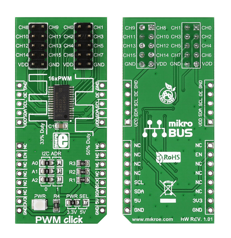
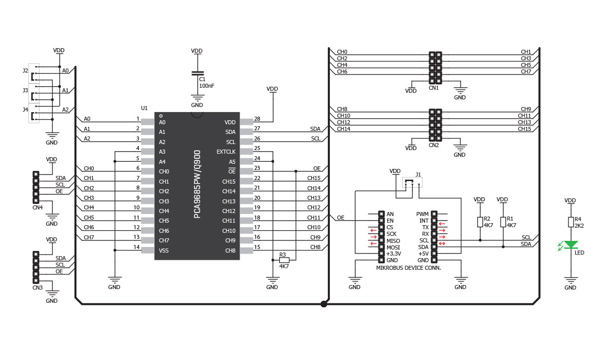
PWM click is a simple solution for controlling 16 PWM outputs through a single I2C interface. The click board carries the PCA9685PW IC. It is designed to use either a 3.3V or 5V power supply. The board also uses a LOW Output Enable Input pin (OE), which is in place of the default mikroBUS RST pin.

No Abuse Reported

Do you want to subscribe in order to receive notifications regarding "PWM Click" changes.

Do you want to unsubscribe in order to stop receiving notifications regarding "PWM Click" changes.

Do you want to report abuse regarding "PWM Click".

  • mikroSDK Library 2.0.0.0
  • Comments (9)
DOWNLOAD LINK RELATED COMPILER CONTAINS
mikroBasic PRO for ARM
  • lib
  • src
  • exa
  • hlp
  • hex
  • sch
  • pcb
  • doc
mikroBasic PRO for AVR
  • lib
  • src
  • exa
  • hlp
  • hex
  • sch
  • pcb
  • doc
mikroBasic PRO for dsPIC30/33 & PIC24
  • lib
  • src
  • exa
  • hlp
  • hex
  • sch
  • pcb
  • doc
mikroBasic PRO for FT90x
  • lib
  • src
  • exa
  • hlp
  • hex
  • sch
  • pcb
  • doc
mikroBasic PRO for PIC
  • lib
  • src
  • exa
  • hlp
  • hex
  • sch
  • pcb
  • doc
mikroBasic PRO for PIC32
  • lib
  • src
  • exa
  • hlp
  • hex
  • sch
  • pcb
  • doc
mikroC PRO for ARM
  • lib
  • src
  • exa
  • hlp
  • hex
  • sch
  • pcb
  • doc
mikroC PRO for AVR
  • lib
  • src
  • exa
  • hlp
  • hex
  • sch
  • pcb
  • doc
mikroC PRO for dsPIC30/33 & PIC24
  • lib
  • src
  • exa
  • hlp
  • hex
  • sch
  • pcb
  • doc
mikroC PRO for FT90x
  • lib
  • src
  • exa
  • hlp
  • hex
  • sch
  • pcb
  • doc
mikroC PRO for PIC
  • lib
  • src
  • exa
  • hlp
  • hex
  • sch
  • pcb
  • doc
mikroC PRO for PIC32
  • lib
  • src
  • exa
  • hlp
  • hex
  • sch
  • pcb
  • doc
mikroPascal PRO for ARM
  • lib
  • src
  • exa
  • hlp
  • hex
  • sch
  • pcb
  • doc
mikroPascal PRO for AVR
  • lib
  • src
  • exa
  • hlp
  • hex
  • sch
  • pcb
  • doc
mikroPascal PRO for dsPIC30/33 & PIC24
  • lib
  • src
  • exa
  • hlp
  • hex
  • sch
  • pcb
  • doc
mikroPascal PRO for FT90x
  • lib
  • src
  • exa
  • hlp
  • hex
  • sch
  • pcb
  • doc
mikroPascal PRO for PIC
  • lib
  • src
  • exa
  • hlp
  • hex
  • sch
  • pcb
  • doc
mikroPascal PRO for PIC32
  • lib
  • src
  • exa
  • hlp
  • hex
  • sch
  • pcb
  • doc

mikroSDK Library Blog

PWM Click

PWM Click

Front and back view of the PWM Click board designed in mikroBUS form factor.

View full image

Library Description

The library covers all the necessary functions that enables the usage of the PWM click board. It initializes and defines the I2C driver and drivers that offer a choice for controlling 16 PWM outputs through a single I2C interface. This library offer functions that allow the user to make controlled PWM output to each and every of 16 channels. It also allows for different configurations and prescaling. Library also offers generic read and write functions for aditional functionality.

Key functions:

  • pwm_devConfig( uint8_t allcall, uint8_t sub3, uint8_t sub2, uint8_t sub1, uint8_t sleep, uint8_t restart ) - Function is used to configure the device.
  • pwm_setChannel( uint8_t channId, uint8_t offset, uint8_t dutyCyc ) - Function is used to specific set channel output with data.
  • pwm_setAll( uint8_t dutyCyc ) - Function is used to set all channels output with data.

Examples description

The application is composed of the three sections :

  • System Initialization - Initializes GPIO, I2C and LOG structures, set RST pin as output.
  • Application Initialization - Initalizes I2C driver, enables output, configures device, sets prescaling, configures output and makes an initial log.
  • Application Task - (code snippet) - This is an example that shows some of the functions that PWM click has.
void applicationTask()
{
    uint16_t rawDc;
    uint8_t channId;
    uint8_t dutyCycle;
    channId = 0;
    mikrobus_logWrite( "Channel 0 false state  ", _LOG_LINE );
    pwm_channelState( channId, 0 );
    mikrobus_logWrite( "--------------------------", _LOG_LINE );
    Delay_ms( 2000 );
    
    mikrobus_logWrite( "Channel 0 set raw  ", _LOG_LINE );
    for ( rawDc = 0; rawDc < PWM_MAX_RESOLUTION; rawDc += 256 )
    {
        pwm_setChannelRaw( channId, 0, rawDc );
        mikrobus_logWrite( " >", _LOG_TEXT );
        Delay_ms( 500 );
    }
    mikrobus_logWrite( "", _LOG_LINE );
    mikrobus_logWrite( "--------------------------", _LOG_LINE );
    Delay_ms( 1000 );
    
    mikrobus_logWrite( "Channel 0 set  ", _LOG_LINE );
    for ( dutyCycle = 0; dutyCycle < 100; dutyCycle += 10 )
    {
        pwm_setChannel( channId, 0, dutyCycle );
        mikrobus_logWrite( " >", _LOG_TEXT );
        Delay_ms( 500 );
    }
    mikrobus_logWrite( "", _LOG_LINE );
    mikrobus_logWrite( "--------------------------", _LOG_LINE );
    Delay_ms( 1000 );
    
    mikrobus_logWrite( "All Channels raw set  ", _LOG_LINE );
    for ( rawDc = 0; rawDc < PWM_MAX_RESOLUTION; rawDc += 256 )
    {
        pwm_setAllRaw( rawDc );
        mikrobus_logWrite( " >", _LOG_TEXT );
        Delay_ms( 500 );
    }
    mikrobus_logWrite( "", _LOG_LINE );
    mikrobus_logWrite( "--------------------------", _LOG_LINE );
    Delay_ms( 1000 );
    
    mikrobus_logWrite( "All Channels set  ", _LOG_LINE );
    for ( dutyCycle = 0; dutyCycle < 100; dutyCycle += 10 )
    {
        pwm_setAll( dutyCycle );
        mikrobus_logWrite( " >", _LOG_TEXT );
        Delay_ms( 500 );
    }
    mikrobus_logWrite( "", _LOG_LINE );
    mikrobus_logWrite( "--------------------------", _LOG_LINE );
    Delay_ms( 1000 );
    
    mikrobus_logWrite( "All Channels false state  ", _LOG_LINE );
    pwm_allChannState( 0 );
    mikrobus_logWrite( "--------------------------", _LOG_LINE );
    Delay_ms( 2000 );
}

Other mikroE Libraries used in the example:

  • I2C
  • UART

Additional notes and informations

Depending on the development board you are using, you may need USB UART clickUSB UART 2 click or RS232 click to connect to your PC, for development systems with no UART to USB interface available on the board. The terminal available in all MikroElektronika compilers, or any other terminal application of your choice, can be used to read the message.

PWM Click Schematics

PWM Click Schematics

Schematics of the PWM click.

View full image

PWM click - example

PWM click is a simple solution for controlling 16 PWM outputs through a single I2C interface. You can use it to control anything from a simple LED strip to a complex robot with a multitude of moving parts. The click boardâ„¢ carries the PCA9685PW IC. The

Watch on YouTube

ALSO FROM THIS AUTHOR

ISM TX click

5

ISM TX Click is a compact add-on board that contains an ASK and (G)FSK transmitter with a programmable SPI interface. This board features the MAX41460, a UHF sub-GHz ISM/SRD transmitter designed to transmit On-Off Keying (OOK), Amplitude- Shift Keying (ASK), Frequency-Shift Keying (FSK), and Gaussian (G)FSK (or 2GFSK) data from Maxim Integrated.

[Learn More]

ADC 19 Click

0

ADC 19 Click is a compact add-on board that contains a high-performance data converter. This board features the ADC122S101, a low-power two-channel CMOS 12-bit analog-to-digital converter from Texas Instruments. This SPI configurable analog-to-digital converter (ADC) is fully specified over a sample rate range of 500ksps to 1Msps, offering high reliability and performance. The converter is based on a successive-approximation register architecture with an internal track-and-hold circuit configurable to accept one or two input signals at its input channels.

[Learn More]

Ambient 20 Click

0

Ambient 20 Click is a compact add-on board used to measure the amount of the present ambient light. This board features the BU27030NUC, a 16-bit digital-output ambient light sensor with an I2C interface from Rohm Semiconductor. The BU27030NUC has a flexible and wide operating range of up to 20klx with a maximum resolution of 0.0007lux/count, providing an excellent responsivity close to the human eyes' response. It also features inherent 50Hz/60Hz light noise rejection and excellent IR-cut characteristics for high robustness at high sensitivity.

[Learn More]