TOP Contributors

  1. MIKROE (2784 codes)
  2. Alcides Ramos (405 codes)
  3. Shawon Shahryiar (307 codes)
  4. jm_palomino (133 codes)
  5. Bugz Bensce (97 codes)
  6. S P (73 codes)
  7. dany (71 codes)
  8. MikroBUS.NET Team (35 codes)
  9. NART SCHINACKOW (34 codes)
  10. Armstrong Subero (27 codes)

Most Downloaded

  1. Timer Calculator (141703 times)
  2. FAT32 Library (74779 times)
  3. Network Ethernet Library (59221 times)
  4. USB Device Library (49226 times)
  5. Network WiFi Library (44999 times)
  6. FT800 Library (44537 times)
  7. GSM click (31203 times)
  8. mikroSDK (30104 times)
  9. microSD click (27586 times)
  10. PID Library (27543 times)
Libstock prefers package manager

Package Manager

We strongly encourage users to use Package manager for sharing their code on Libstock website, because it boosts your efficiency and leaves the end user with no room for error. [more info]

< Back
mikroSDK Library

Comparator click

Rating:

5

Author: MIKROE

Last Updated: 2019-04-02

Package Version: 1.0.0.1

mikroSDK Library: 1.0.0.0

Category: ADC

Downloaded: 5680 times

Followed by: 4 users

License: MIT license  

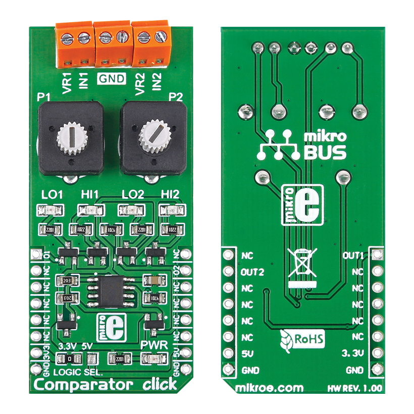
Comparator click can be used with a single or dual power supply. If a single power supply is used, the offset voltage can be as low as 2.0 mV, with a range from 2.0 VDC to 36 VDC. For dual supplies, the range is from ±1.0 VDC to ±18 VDC. The resulting output is compatible with TTL, DTL, ECL, MOS and CMOS logic systems.

No Abuse Reported

Do you want to subscribe in order to receive notifications regarding "Comparator click" changes.

Do you want to unsubscribe in order to stop receiving notifications regarding "Comparator click" changes.

Do you want to report abuse regarding "Comparator click".

  • mikroSDK Library 2.0.0.0
  • Comments (0)
DOWNLOAD LINK RELATED COMPILER CONTAINS
mikroBasic PRO for ARM
  • lib
  • src
  • exa
  • hlp
  • hex
  • sch
  • pcb
  • doc
mikroBasic PRO for AVR
  • lib
  • src
  • exa
  • hlp
  • hex
  • sch
  • pcb
  • doc
mikroBasic PRO for dsPIC30/33 & PIC24
  • lib
  • src
  • exa
  • hlp
  • hex
  • sch
  • pcb
  • doc
mikroBasic PRO for FT90x
  • lib
  • src
  • exa
  • hlp
  • hex
  • sch
  • pcb
  • doc
mikroBasic PRO for PIC
  • lib
  • src
  • exa
  • hlp
  • hex
  • sch
  • pcb
  • doc
mikroBasic PRO for PIC32
  • lib
  • src
  • exa
  • hlp
  • hex
  • sch
  • pcb
  • doc
mikroC PRO for ARM
  • lib
  • src
  • exa
  • hlp
  • hex
  • sch
  • pcb
  • doc
mikroC PRO for AVR
  • lib
  • src
  • exa
  • hlp
  • hex
  • sch
  • pcb
  • doc
mikroC PRO for dsPIC30/33 & PIC24
  • lib
  • src
  • exa
  • hlp
  • hex
  • sch
  • pcb
  • doc
mikroC PRO for FT90x
  • lib
  • src
  • exa
  • hlp
  • hex
  • sch
  • pcb
  • doc
mikroC PRO for PIC
  • lib
  • src
  • exa
  • hlp
  • hex
  • sch
  • pcb
  • doc
mikroC PRO for PIC32
  • lib
  • src
  • exa
  • hlp
  • hex
  • sch
  • pcb
  • doc
mikroPascal PRO for ARM
  • lib
  • src
  • exa
  • hlp
  • hex
  • sch
  • pcb
  • doc
mikroPascal PRO for AVR
  • lib
  • src
  • exa
  • hlp
  • hex
  • sch
  • pcb
  • doc
mikroPascal PRO for dsPIC30/33 & PIC24
  • lib
  • src
  • exa
  • hlp
  • hex
  • sch
  • pcb
  • doc
mikroPascal PRO for FT90x
  • lib
  • src
  • exa
  • hlp
  • hex
  • sch
  • pcb
  • doc
mikroPascal PRO for PIC
  • lib
  • src
  • exa
  • hlp
  • hex
  • sch
  • pcb
  • doc
mikroPascal PRO for PIC32
  • lib
  • src
  • exa
  • hlp
  • hex
  • sch
  • pcb
  • doc

mikroSDK Library Blog

Comparator Click Board

Comparator Click Board

Front and back side of the Comparator Click Board

View full image

Library Description

The library covers all the necessary functions to control the Comparator click board. Comparator click communicates with the device via GPIO driver. This library contains drivers for check state of the OUT1 and OUT2 pin function.

Key functions:

  • uint8_t comparator_checkOutputOne() - Check state of the OUT1 pin function.
  • uint8_t comparator_checkOutputTwo() - Check state of the OUT2 pin function.

Examples description

The application is composed of three sections:

  • System Initialization - Initializes GPIO and LOG structures, sets AN and INT pins as input and start to write log.
  • Application Initialization -  Initialization driver enables - GPIO also, write log.
  • Application Task - (code snippet) This is an example which demonstrates the use of Comparator click board. Comparator clicks checks state of the OUT1 and OUT2 pins. Results are being sent to the Usart Terminal where you can track their changes. All data logs write on USB uart changes for every 1 sec.
void applicationTask() 
{
    outStateOne = comparator_checkOutputOne();
    outStateTwo = comparator_checkOutputTwo();
    
    mikrobus_logWrite( " Output One : ", _LOG_TEXT );
    
    if ( outStateOne )
        mikrobus_logWrite( "High", _LOG_LINE );
    else
        mikrobus_logWrite( "Low", _LOG_LINE );

    mikrobus_logWrite( " Output Two : ", _LOG_TEXT );

    if ( outStateTwo )
        mikrobus_logWrite( "High", _LOG_LINE );
    else
        mikrobus_logWrite( "Low", _LOG_LINE );
    
    mikrobus_logWrite( "-------------------", _LOG_LINE );
    Delay_1sec();
}       

Other mikroE Libraries used in the example:

  • GPIO
  • UART​
  • Conversion

Additional notes and informations

Depending on the development board you are using, you may need USB UART clickUSB UART 2 click or RS232 click to connect to your PC, for development systems with no UART to USB interface available on the board. The terminal available in all MikroElektronika compilers, or any other terminal application of your choice, can be used to read the message

ALSO FROM THIS AUTHOR

Dot Matrix R Click

0

Dot Matrix R Click is a display device Click board™ based on a four-digit dot matrix display module, labeled as HCMS-3906 from a company Avago (Broadcom Inc).

[Learn More]

LR 3 Click

0

LR 3 Click is a compact add-on board that contains a long-range transceiver. This board features the 32001345, RF technology-based SRD transceiver, which operates at a frequency of 868MHz from Mipot.

[Learn More]

Relay 2 click

5

Relay 2 click carries two LCA717 single-pole, OptoMOS® solid state relays and two screw terminals for connecting the wiring. They are controlled by the microcontroller through RL1 and RL2 pins, which are in place of default mikroBUS AN and PWM pins.

[Learn More]