TOP Contributors

  1. MIKROE (2663 codes)
  2. Alcides Ramos (358 codes)
  3. Shawon Shahryiar (307 codes)
  4. jm_palomino (112 codes)
  5. Chisanga Mumba (90 codes)
  6. S P (73 codes)
  7. dany (71 codes)
  8. MikroBUS.NET Team (35 codes)
  9. NART SCHINACKOW (34 codes)
  10. Armstrong Subero (27 codes)

Most Downloaded

  1. Timer Calculator (137084 times)
  2. FAT32 Library (70227 times)
  3. Network Ethernet Library (56097 times)
  4. USB Device Library (46428 times)
  5. Network WiFi Library (42042 times)
  6. FT800 Library (41382 times)
  7. GSM click (29110 times)
  8. mikroSDK (26558 times)
  9. PID Library (26487 times)
  10. microSD click (25486 times)
Libstock prefers package manager

Package Manager

We strongly encourage users to use Package manager for sharing their code on Libstock website, because it boosts your efficiency and leaves the end user with no room for error. [more info]

< Back
mikroSDK Library

Ammeter click

Rating:

1

Author: MIKROE

Last Updated: 2019-05-03

Package Version: 1.0.0.1

mikroSDK Library: 1.0.0.0

Category: Measurements

Downloaded: 3957 times

Not followed.

License: MIT license  

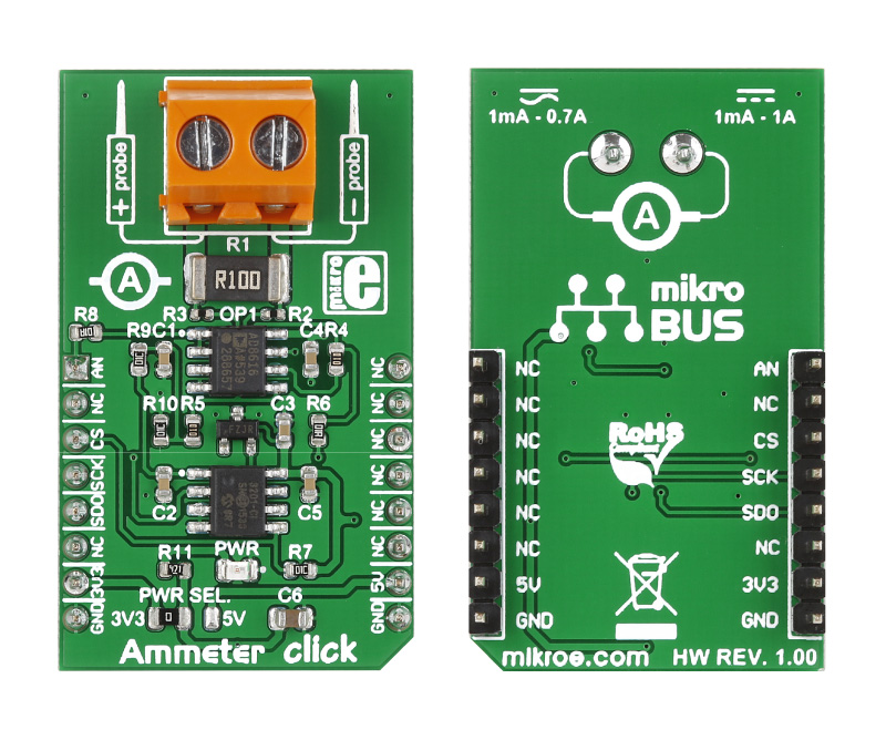
Ammeter click is a mikroBUS add-on board with circuitry for measuring electric current ( both AC and DC ).

No Abuse Reported

Do you want to subscribe in order to receive notifications regarding "Ammeter click" changes.

Do you want to unsubscribe in order to stop receiving notifications regarding "Ammeter click" changes.

Do you want to report abuse regarding "Ammeter click".

  • mikroSDK Library 2.0.0.0
  • Comments (3)
DOWNLOAD LINK RELATED COMPILER CONTAINS
mikroBasic PRO for ARM
  • lib
  • src
  • exa
  • hlp
  • hex
  • sch
  • pcb
  • doc
mikroBasic PRO for AVR
  • lib
  • src
  • exa
  • hlp
  • hex
  • sch
  • pcb
  • doc
mikroBasic PRO for dsPIC30/33 & PIC24
  • lib
  • src
  • exa
  • hlp
  • hex
  • sch
  • pcb
  • doc
mikroBasic PRO for FT90x
  • lib
  • src
  • exa
  • hlp
  • hex
  • sch
  • pcb
  • doc
mikroBasic PRO for PIC
  • lib
  • src
  • exa
  • hlp
  • hex
  • sch
  • pcb
  • doc
mikroBasic PRO for PIC32
  • lib
  • src
  • exa
  • hlp
  • hex
  • sch
  • pcb
  • doc
mikroC PRO for ARM
  • lib
  • src
  • exa
  • hlp
  • hex
  • sch
  • pcb
  • doc
mikroC PRO for AVR
  • lib
  • src
  • exa
  • hlp
  • hex
  • sch
  • pcb
  • doc
mikroC PRO for dsPIC30/33 & PIC24
  • lib
  • src
  • exa
  • hlp
  • hex
  • sch
  • pcb
  • doc
mikroC PRO for FT90x
  • lib
  • src
  • exa
  • hlp
  • hex
  • sch
  • pcb
  • doc
mikroC PRO for PIC
  • lib
  • src
  • exa
  • hlp
  • hex
  • sch
  • pcb
  • doc
mikroC PRO for PIC32
  • lib
  • src
  • exa
  • hlp
  • hex
  • sch
  • pcb
  • doc
mikroPascal PRO for ARM
  • lib
  • src
  • exa
  • hlp
  • hex
  • sch
  • pcb
  • doc
mikroPascal PRO for AVR
  • lib
  • src
  • exa
  • hlp
  • hex
  • sch
  • pcb
  • doc
mikroPascal PRO for dsPIC30/33 & PIC24
  • lib
  • src
  • exa
  • hlp
  • hex
  • sch
  • pcb
  • doc
mikroPascal PRO for FT90x
  • lib
  • src
  • exa
  • hlp
  • hex
  • sch
  • pcb
  • doc
mikroPascal PRO for PIC
  • lib
  • src
  • exa
  • hlp
  • hex
  • sch
  • pcb
  • doc
mikroPascal PRO for PIC32
  • lib
  • src
  • exa
  • hlp
  • hex
  • sch
  • pcb
  • doc

mikroSDK Library Blog

Front / Back View

Front / Back View

Ammeter front and back view

View full image

Library Description

The library covers all the necessary functions that enables the usage of the Ammeter click board.
It offers reading from output register and calculations that result in relatively accurate amperage value.

Key functions:

  • uint16_t ammeter_amperage() - Function is used to measure amperage of a power consumer connected to the click board.
  • uint16_t ammeter_getRawData() - Function is used to read raw data value from output register.
  • uint16_t ammeter_dataRead() - Function is used to read data from output register.

Examples description

The application is composed of the three sections :

  • System Initialization - Initializes SPI module, LOG and GPIO structures, sets CS pin as output and AN pin as input.
  • Application Initialization - Initalizes SPI driver and makes an initial log.
  • Application Task - This is an example that shows the capabilities of the Ammeter click by measuring amperage in miliampers. Ammeter click board can be used to saftly measure current up to 1A both AC and DC, in the case of AC, for peak to peak value. It is important to notice that this click board has its' own electronic circuit, and may not be powered from the same source which we are measuring. Result will not be correct in that case.
void applicationTask( )
{
    amperage = ammeter_amperage();
    IntToStr( amperage, logTxt );
    mikrobus_logWrite( " Amperage: ", _LOG_TEXT );
    mikrobus_logWrite( logTxt, _LOG_TEXT );
    mikrobus_logWrite( "mA ", _LOG_LINE );
    mikrobus_logWrite( "-----------------------", _LOG_LINE );
    Delay_ms( 1000 );
}

Other mikroE Libraries used in the example:

  • SPI
  • UART
  • Conversions

Additional notes and informations

Depending on the development board you are using, you may need USB UART clickUSB UART 2 click or RS232 click to connect to your PC, for development systems with no UART to USB interface available on the board. The terminal available in all MikroElektronika compilers, or any other terminal application of your choice, can be used to read the message.

Schematic

Schematic

Ammeter click schematic

View full image

ALSO FROM THIS AUTHOR

DIGI POT 6 click

5

DIGI POT 6 Click features the MCP41HVX1 family of devices which have dual power rails (analog and digital). The analog power rail allows high voltage on the resistor network terminal pins. The analog voltage range is determined by the V+ and V- voltages.

[Learn More]

Matrix R click

0

Matrix R click is a mikroBUS add-on board with two red 5x7 matrices driven by two MAX7219 8-bit LED Display Drivers. The active area of each matrix is 7.62mm high and 5.08 mm wide. 7x5 is a standard resolution for displaying ASCII characters, so the click is essentially a dual-character display capable of showing letters in more readable typefaces compared to a 14-segment display. The click communicates with the target MCU through the mikroBUS:tm: SPI interface with two separate Chip Select lines for each matrix (CSL for the left, CSR for the right). This board is designed to use a 5V power supply.

[Learn More]

LTE IoT 2 click

5

LTE IoT 2 click is a Click board that allows connection to the LTE networks, featuring Quectel BG96 LTE module, which offers two LTE technologies aimed at Machine to Machine communication (M2M) and Internet of Things (IoT).

[Learn More]