TOP Contributors

  1. MIKROE (2784 codes)
  2. Alcides Ramos (403 codes)
  3. Shawon Shahryiar (307 codes)
  4. jm_palomino (130 codes)
  5. Bugz Bensce (97 codes)
  6. S P (73 codes)
  7. dany (71 codes)
  8. MikroBUS.NET Team (35 codes)
  9. NART SCHINACKOW (34 codes)
  10. Armstrong Subero (27 codes)

Most Downloaded

  1. Timer Calculator (140903 times)
  2. FAT32 Library (73485 times)
  3. Network Ethernet Library (58269 times)
  4. USB Device Library (48468 times)
  5. Network WiFi Library (44078 times)
  6. FT800 Library (43632 times)
  7. GSM click (30522 times)
  8. mikroSDK (29253 times)
  9. PID Library (27196 times)
  10. microSD click (26908 times)
Libstock prefers package manager

Package Manager

We strongly encourage users to use Package manager for sharing their code on Libstock website, because it boosts your efficiency and leaves the end user with no room for error. [more info]

< Back
Example

Hz to V click

Rating:

5

Author: MIKROE

Last Updated: 2018-03-09

Package Version: 1.0.0.0

Example: 1.0.0.0

Category: Measurements

Downloaded: 5032 times

Not followed.

License: MIT license  

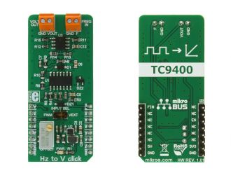
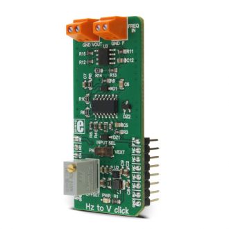
HZ to V click is a device that can convert input frequency of the signal with virtually any wave shape to a DC voltage output, with a level proportional to the input frequency.

No Abuse Reported

Do you want to subscribe in order to receive notifications regarding "Hz to V click" changes.

Do you want to unsubscribe in order to stop receiving notifications regarding "Hz to V click" changes.

Do you want to report abuse regarding "Hz to V click".
  • mikroSDK Library 2.0.0.0
  • Comments (0)
DOWNLOAD LINK RELATED COMPILER CONTAINS
mikroBasic PRO for ARM
  • lib
  • src
  • exa
  • hlp
  • hex
  • sch
  • pcb
  • doc
mikroBasic PRO for AVR
  • lib
  • src
  • exa
  • hlp
  • hex
  • sch
  • pcb
  • doc
mikroBasic PRO for dsPIC30/33 & PIC24
  • lib
  • src
  • exa
  • hlp
  • hex
  • sch
  • pcb
  • doc
mikroBasic PRO for FT90x
  • lib
  • src
  • exa
  • hlp
  • hex
  • sch
  • pcb
  • doc
mikroBasic PRO for PIC
  • lib
  • src
  • exa
  • hlp
  • hex
  • sch
  • pcb
  • doc
mikroBasic PRO for PIC32
  • lib
  • src
  • exa
  • hlp
  • hex
  • sch
  • pcb
  • doc
mikroC PRO for ARM
  • lib
  • src
  • exa
  • hlp
  • hex
  • sch
  • pcb
  • doc
mikroC PRO for AVR
  • lib
  • src
  • exa
  • hlp
  • hex
  • sch
  • pcb
  • doc
mikroC PRO for dsPIC30/33 & PIC24
  • lib
  • src
  • exa
  • hlp
  • hex
  • sch
  • pcb
  • doc
mikroC PRO for FT90x
  • lib
  • src
  • exa
  • hlp
  • hex
  • sch
  • pcb
  • doc
mikroC PRO for PIC
  • lib
  • src
  • exa
  • hlp
  • hex
  • sch
  • pcb
  • doc
mikroC PRO for PIC32
  • lib
  • src
  • exa
  • hlp
  • hex
  • sch
  • pcb
  • doc
mikroPascal PRO for ARM
  • lib
  • src
  • exa
  • hlp
  • hex
  • sch
  • pcb
  • doc
mikroPascal PRO for AVR
  • lib
  • src
  • exa
  • hlp
  • hex
  • sch
  • pcb
  • doc
mikroPascal PRO for dsPIC30/33 & PIC24
  • lib
  • src
  • exa
  • hlp
  • hex
  • sch
  • pcb
  • doc
mikroPascal PRO for FT90x
  • lib
  • src
  • exa
  • hlp
  • hex
  • sch
  • pcb
  • doc
mikroPascal PRO for PIC
  • lib
  • src
  • exa
  • hlp
  • hex
  • sch
  • pcb
  • doc
mikroPascal PRO for PIC32
  • lib
  • src
  • exa
  • hlp
  • hex
  • sch
  • pcb
  • doc

Example Blog

Hz to V click

Hz to V click

Native view of the Hz to V click board.

View full image
Hz to V click

Hz to V click

Front and back view of the Hz to V click board.

View full image

Examples Description

The demo application shows how to control the Hz to V click using MCU's PWM module.
The demo application is composed of two sections:

  • Application Task - Alternates between different output voltages.
  • hz2v_setOutputVoltage - Sets the PWM frequency to the required value, changing the output voltage.
//Sets the output voltage in millivolts
void hz2v_setOutputVoltage(uint16_t voltage)
{
 pwmPeriod = PWM_TIM5_Init(voltage*2);
 PWM_TIM5_Set_Duty(pwmPeriod/2, _PWM_NON_INVERTED, _PWM_CHANNEL1);
 PWM_TIM5_Start(_PWM_CHANNEL1, &_GPIO_MODULE_TIM5_CH1_PA0);
}

void applicationTask()
{
 hz2v_setOutputVoltage(5000); //5 V output
 Delay_ms(3000);
 hz2v_setOutputVoltage(2500); //2.5 V output
 Delay_ms(3000);
 hz2v_setOutputVoltage(1000); //1 V output
 Delay_ms(3000);
 hz2v_setOutputVoltage(500); //0.5 V output
 Delay_ms(3000);
}


Other MikroElektronika Libraries used in the example:

  • PWM

Additional notes and information

Depending on the development board you are using, you may need USB UART clickUSB UART 2 click or  RS232 click to connect to your PC, for development systems with no UART to USB interface available on the board. The terminal available in all MikroElektronika compilers, or any other terminal application of your choice, can be used to read the message.

ALSO FROM THIS AUTHOR

IPS Display Click

0

IPS Display Click is a compact add-on board that displays high-resolution graphics in embedded applications. This board features the ER-TFT1.14-2, a 1.14inch TFT LCD display from BuyDisplay, part of EastRising Technology, and utilizes the ST7789V controller for 262K color output. The display offers a 135x240 pixel resolution, operates through a 3-wire SPI interface, and includes additional control lines such as RST and RS for precise display management. Its small form factor and high-resolution output make it suitable for various projects, including handheld devices, smart displays, and control panels requiring clear visual output.

[Learn More]

ADC click

0

Simple example which demonstrates working with the 4-Channel 12-bit A/D Converter (MCP3204) with SPI Serial Interface. The example shows how to measure analog inputs on Channels 0, 1, 2 and 3 and display the results on LCD.

[Learn More]

ATA6570 click

0

ATA6570 click is an automotive diagnostic tool that allows CAN bus interfacing, in a series of click boards aimed towards automotive diagnostics.

[Learn More]