TOP Contributors

  1. MIKROE (2784 codes)
  2. Alcides Ramos (405 codes)
  3. Shawon Shahryiar (307 codes)
  4. jm_palomino (133 codes)
  5. Bugz Bensce (97 codes)
  6. S P (73 codes)
  7. dany (71 codes)
  8. MikroBUS.NET Team (35 codes)
  9. NART SCHINACKOW (34 codes)
  10. Armstrong Subero (27 codes)

Most Downloaded

  1. Timer Calculator (141481 times)
  2. FAT32 Library (74335 times)
  3. Network Ethernet Library (58869 times)
  4. USB Device Library (48921 times)
  5. Network WiFi Library (44698 times)
  6. FT800 Library (44227 times)
  7. GSM click (30937 times)
  8. mikroSDK (29817 times)
  9. PID Library (27423 times)
  10. microSD click (27375 times)
Libstock prefers package manager

Package Manager

We strongly encourage users to use Package manager for sharing their code on Libstock website, because it boosts your efficiency and leaves the end user with no room for error. [more info]

< Back
mikroSDK Library

LED Driver 4 click

Rating:

5

Author: MIKROE

Last Updated: 2018-06-01

Package Version: 1.0.0.0

mikroSDK Library: 1.0.0.0

Category: LED Drivers

Downloaded: 5007 times

Not followed.

License: MIT license  

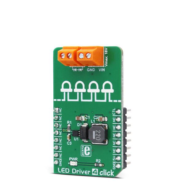
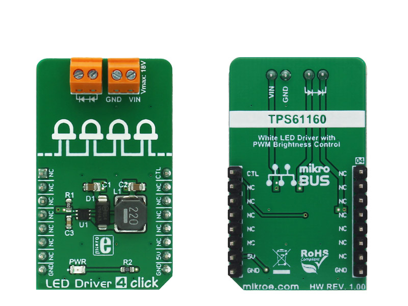
LED Driver 4 click is a form of a high-efficiency boost converter that is ideally suited for driving an array of white LEDs. The driver has the ability to dim the connected LED array, without producing any noise on the output.

No Abuse Reported

Do you want to subscribe in order to receive notifications regarding "LED Driver 4 click" changes.

Do you want to unsubscribe in order to stop receiving notifications regarding "LED Driver 4 click" changes.

Do you want to report abuse regarding "LED Driver 4 click".

  • mikroSDK Library 2.0.0.0
  • Comments (0)
DOWNLOAD LINK RELATED COMPILER CONTAINS
mikroBasic PRO for ARM
  • lib
  • src
  • exa
  • hlp
  • hex
  • sch
  • pcb
  • doc
mikroBasic PRO for AVR
  • lib
  • src
  • exa
  • hlp
  • hex
  • sch
  • pcb
  • doc
mikroBasic PRO for dsPIC30/33 & PIC24
  • lib
  • src
  • exa
  • hlp
  • hex
  • sch
  • pcb
  • doc
mikroBasic PRO for FT90x
  • lib
  • src
  • exa
  • hlp
  • hex
  • sch
  • pcb
  • doc
mikroBasic PRO for PIC
  • lib
  • src
  • exa
  • hlp
  • hex
  • sch
  • pcb
  • doc
mikroBasic PRO for PIC32
  • lib
  • src
  • exa
  • hlp
  • hex
  • sch
  • pcb
  • doc
mikroC PRO for ARM
  • lib
  • src
  • exa
  • hlp
  • hex
  • sch
  • pcb
  • doc
mikroC PRO for AVR
  • lib
  • src
  • exa
  • hlp
  • hex
  • sch
  • pcb
  • doc
mikroC PRO for dsPIC30/33 & PIC24
  • lib
  • src
  • exa
  • hlp
  • hex
  • sch
  • pcb
  • doc
mikroC PRO for FT90x
  • lib
  • src
  • exa
  • hlp
  • hex
  • sch
  • pcb
  • doc
mikroC PRO for PIC
  • lib
  • src
  • exa
  • hlp
  • hex
  • sch
  • pcb
  • doc
mikroC PRO for PIC32
  • lib
  • src
  • exa
  • hlp
  • hex
  • sch
  • pcb
  • doc
mikroPascal PRO for ARM
  • lib
  • src
  • exa
  • hlp
  • hex
  • sch
  • pcb
  • doc
mikroPascal PRO for AVR
  • lib
  • src
  • exa
  • hlp
  • hex
  • sch
  • pcb
  • doc
mikroPascal PRO for dsPIC30/33 & PIC24
  • lib
  • src
  • exa
  • hlp
  • hex
  • sch
  • pcb
  • doc
mikroPascal PRO for FT90x
  • lib
  • src
  • exa
  • hlp
  • hex
  • sch
  • pcb
  • doc
mikroPascal PRO for PIC
  • lib
  • src
  • exa
  • hlp
  • hex
  • sch
  • pcb
  • doc
mikroPascal PRO for PIC32
  • lib
  • src
  • exa
  • hlp
  • hex
  • sch
  • pcb
  • doc

mikroSDK Library Blog

LED Driver 4 click

LED Driver 4 click

Native view of the LED Driver 4 click board.

View full image
LED Driver 4 click

LED Driver 4 click

Front and back view of the LED Driver 4 click board.

View full image

Library Description

The library carries functions necessary to have complete control over all functionalities of the Click board.

Examples Description

The demo application is composed of three sections:

  • System Initialization - Necessary registers and GPIO configuration.
  • Application Initialization - PWM Initizalization and Start of PWM signal.
  • Application Task - (code snippet) - Sequential change of the brightness from
    minimum to maximum value.
void applicationTask()
{
 dutyCycle += 50;
 PWM_TIM5_Set_Duty(dutyCycle, _PWM_NON_INVERTED, _PWM_CHANNEL1);
 if (dutyCycle > pwmPeriod )
 dutyCycle = 0;
 Delay_ms(2);
}

Other mikroE Libraries used in the example:

  • PWM

Additional notes and information

Depending on the development board you are using, you may need USB UART click,  USB UART 2 click or RS232 click to connect to your PC, for development systems with no UART to USB interface available on the board. The terminal available in all MikroElektronika compilers, or any other terminal application of your choice, can be used to read the message.

ALSO FROM THIS AUTHOR

GSM/GNSS 2 click

0

GSM/GNSS 2 click combines GPS/GLONASS location tracking with GSM module capability for mobile communication. The click carries SIM868 quad-band GSM/GPRS module which combines GNSS technology for satellite navigation.

[Learn More]

iButton Click

0

iButton Click - is an iButton™ probe Click board™. The iButton is a Analog Devices technology based on Analog's 1-Wire® communication protocol, and a chip usually packed in a robust stainless steel casing. The button-shaped iButton device has two contacts - the lid and the base. These contacts carry the necessary connections down to a sensitive silicone chip, embedded inside the metal button. When the iButton touches the reader probe on the Click board™, it establishes the communication with the host MCU, via the 1-Wire® interface. The communication is almost instant, so it is enough to press the iButton lightly to the probe contacts.

[Learn More]

LED Ring R Click

1

LED ring R click is a mikroBUS add-on board with a ring of 32 red LEDs driven by four 8-bit 74HC595 serial-in, parallel-out shift registers. The ring is 25 mm in diameter. The click communicates with the target MCU through the mikroBUS SPI interface, with RST, CS, SCK, MISO and MOSI pins marked MR#, LAT, CLK, DSOUT, DSIN, respectively.

[Learn More]