TOP Contributors

  1. MIKROE (2784 codes)
  2. Alcides Ramos (405 codes)
  3. Shawon Shahryiar (307 codes)
  4. jm_palomino (133 codes)
  5. Bugz Bensce (97 codes)
  6. S P (73 codes)
  7. dany (71 codes)
  8. MikroBUS.NET Team (35 codes)
  9. NART SCHINACKOW (34 codes)
  10. Armstrong Subero (27 codes)

Most Downloaded

  1. Timer Calculator (141478 times)
  2. FAT32 Library (74335 times)
  3. Network Ethernet Library (58867 times)
  4. USB Device Library (48921 times)
  5. Network WiFi Library (44698 times)
  6. FT800 Library (44227 times)
  7. GSM click (30937 times)
  8. mikroSDK (29817 times)
  9. PID Library (27423 times)
  10. microSD click (27375 times)
Libstock prefers package manager

Package Manager

We strongly encourage users to use Package manager for sharing their code on Libstock website, because it boosts your efficiency and leaves the end user with no room for error. [more info]

< Back
mikroSDK Library

VREG 2 click

Rating:

5

Author: MIKROE

Last Updated: 2018-06-22

Package Version: 1.0.0.0

mikroSDK Library: 1.0.0.0

Category: Buck

Downloaded: 5254 times

Not followed.

License: MIT license  

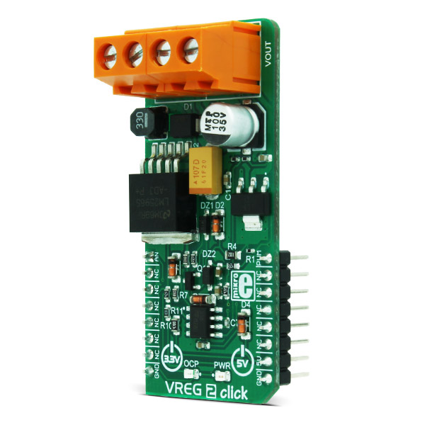
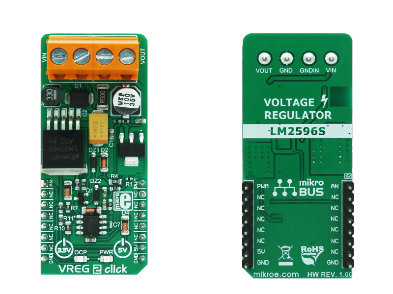
VREG 2 click is a voltage regulator click, with outstanding performances. It has a steady output voltage with the ripple lower than 5mV, short circuit protection with the LED indicator, and high efficiency with minimal power dissipation.

No Abuse Reported

Do you want to subscribe in order to receive notifications regarding "VREG 2 click" changes.

Do you want to unsubscribe in order to stop receiving notifications regarding "VREG 2 click" changes.

Do you want to report abuse regarding "VREG 2 click".

  • mikroSDK Library 2.0.0.0
  • Comments (0)
DOWNLOAD LINK RELATED COMPILER CONTAINS
mikroBasic PRO for ARM
  • lib
  • src
  • exa
  • hlp
  • hex
  • sch
  • pcb
  • doc
mikroBasic PRO for AVR
  • lib
  • src
  • exa
  • hlp
  • hex
  • sch
  • pcb
  • doc
mikroBasic PRO for dsPIC30/33 & PIC24
  • lib
  • src
  • exa
  • hlp
  • hex
  • sch
  • pcb
  • doc
mikroBasic PRO for FT90x
  • lib
  • src
  • exa
  • hlp
  • hex
  • sch
  • pcb
  • doc
mikroBasic PRO for PIC
  • lib
  • src
  • exa
  • hlp
  • hex
  • sch
  • pcb
  • doc
mikroBasic PRO for PIC32
  • lib
  • src
  • exa
  • hlp
  • hex
  • sch
  • pcb
  • doc
mikroC PRO for ARM
  • lib
  • src
  • exa
  • hlp
  • hex
  • sch
  • pcb
  • doc
mikroC PRO for AVR
  • lib
  • src
  • exa
  • hlp
  • hex
  • sch
  • pcb
  • doc
mikroC PRO for dsPIC30/33 & PIC24
  • lib
  • src
  • exa
  • hlp
  • hex
  • sch
  • pcb
  • doc
mikroC PRO for FT90x
  • lib
  • src
  • exa
  • hlp
  • hex
  • sch
  • pcb
  • doc
mikroC PRO for PIC
  • lib
  • src
  • exa
  • hlp
  • hex
  • sch
  • pcb
  • doc
mikroC PRO for PIC32
  • lib
  • src
  • exa
  • hlp
  • hex
  • sch
  • pcb
  • doc
mikroPascal PRO for ARM
  • lib
  • src
  • exa
  • hlp
  • hex
  • sch
  • pcb
  • doc
mikroPascal PRO for AVR
  • lib
  • src
  • exa
  • hlp
  • hex
  • sch
  • pcb
  • doc
mikroPascal PRO for dsPIC30/33 & PIC24
  • lib
  • src
  • exa
  • hlp
  • hex
  • sch
  • pcb
  • doc
mikroPascal PRO for FT90x
  • lib
  • src
  • exa
  • hlp
  • hex
  • sch
  • pcb
  • doc
mikroPascal PRO for PIC
  • lib
  • src
  • exa
  • hlp
  • hex
  • sch
  • pcb
  • doc
mikroPascal PRO for PIC32
  • lib
  • src
  • exa
  • hlp
  • hex
  • sch
  • pcb
  • doc

mikroSDK Library Blog

VREG 2 click

VREG 2 click

Native view of the VREG 2 click board.

View full image
VREG 2 click

VREG 2 click

Front and back view of the VREG 2 click board.

View full image

This library provides parsing functions that will allow a user to control the voltage output by inputting user-defined parameters.

Key functions:

  • void vreg2_workParameters(uint8_t setA, uint8_t setB, uint8_t setC, uint8_t setD) - Function for setting work parameters for setting the output voltage in %.
  • int8_t vreg2_incHandler(uint8_t *in); - If the setA parameter has been received this function will return the value of 1.
  • int8_t vreg2_decHandler(uint8_t *in); - If the setB parameter has been received this function will return the value of -1.
  • uint8_t vreg2_printHandler(uint16_t *pwm); - This function returns flags based on the internal parser state.

Examples Description

The application is composed of three sections:

  • System Initialization - Initializes GPIO structures.
  • Application Initialization - Initializes the GPIO driver and configures the PWM
    peripheral for controlling VREG2 voltage output.
  • Application Task - (code snippet) - Based on the data received from the UART
    the voltage output will be increased or decreased.
void applicationTask()
{
 if( UART_Rdy_Ptr() )
 {
 rxDat[0] = UART_Rd_Ptr();
 vreg2_eventTick();
 }

 pwmDuty += vreg2_incHandler( &rxDat );
 pwmDuty += vreg2_decHandler( &rxDat ); 
 vreg2_parseInput( &rxDat, &parseVoltage[0] , &pwmDuty );
 temp = vreg2_printHandler( &pwmDuty );

 if( temp == VREG2_VOLTAGE_SET )
 {
 WordToStr( pwmDuty, text );
 mikrobus_logWrite( "Voltage set to : ", _LOG_TEXT );
 mikrobus_logWrite( text, _LOG_TEXT );
 mikrobus_logWrite( " %", _LOG_LINE );
 }
 if( temp == VREG2_BACKSPACE_PRESSED_HANDLE )
 {
 mikrobus_logWrite( " ", _LOG_LINE );
 mikrobus_logWrite( parseVoltage, _LOG_TEXT );
 }
 if( temp == VREG2_CHARACTER_RECEIVED )
 {
 mikrobus_logWrite(rxDat,_LOG_TEXT);
 }
 if( temp == VREG2_NUMBER_PARSER_ENABLED )
 {
 mikrobus_logWrite( "Insert value from 1 to 99%", _LOG_LINE );
 }

 vreg2_set( pwmDuty );
 rxDat[0] = 0;
}

Additional Functions:

  • void vreg2_set(uint16_t pwmIn) - Set's the PWM output from 0 to 100%.
  • void vreg2_pwmInit() - Initializes the PWM peripheral.

The full application code, and ready to use projects can be found on our Libstock page.

Other mikroE Libraries used in the example:

  • PWM Library
  • UART Library
  • Conversions Library
  • C_String Library

Additional notes and information

Depending on the development board you are using, you may need USB UART click,  USB UART 2 click or RS232 click to connect to your PC, for development systems with no UART to USB interface available on the board. The terminal available in all MikroElektronika compilers, or any other terminal application of your choice, can be used to read the message.

ALSO FROM THIS AUTHOR

DALI 3.3V click - Example

1

This example demonstrates use of DALI protocol for controlling leds on board. There are two DALI click cards which allow protocol communication.

[Learn More]

UT-L 7-SEG B Click

0

UT-L 7-SEG B Click is a compact add-on board that presents an easy solution for adding a numeric or hexadecimal display to your application. This board features two blue JSS-5611BUB-21s, ultra-thin single-digit numeric displays from Ningbo Junsheng Electronics. The displays are medium (0.56 inches in height) and can display letters, numbers, and symbols in a highly readable form. The host MCU can control the light intensity of the red segments of the display.

[Learn More]

Relay click

0

Relay click is a dual relay Click board, which can be operated by the host MCU. This Click board offers an elegant and easy solution for controlling a wide range of high power applications.

[Learn More]