TOP Contributors

  1. MIKROE (2784 codes)
  2. Alcides Ramos (402 codes)
  3. Shawon Shahryiar (307 codes)
  4. jm_palomino (129 codes)
  5. Bugz Bensce (97 codes)
  6. S P (73 codes)
  7. dany (71 codes)
  8. MikroBUS.NET Team (35 codes)
  9. NART SCHINACKOW (34 codes)
  10. Armstrong Subero (27 codes)

Most Downloaded

  1. Timer Calculator (140767 times)
  2. FAT32 Library (73351 times)
  3. Network Ethernet Library (58197 times)
  4. USB Device Library (48380 times)
  5. Network WiFi Library (43975 times)
  6. FT800 Library (43537 times)
  7. GSM click (30466 times)
  8. mikroSDK (29170 times)
  9. PID Library (27166 times)
  10. microSD click (26847 times)
Libstock prefers package manager

Package Manager

We strongly encourage users to use Package manager for sharing their code on Libstock website, because it boosts your efficiency and leaves the end user with no room for error. [more info]

< Back
mikroSDK Library

Relay click

Rating:

0

Author: MIKROE

Last Updated: 2018-03-09

Package Version: 1.0.0.1

mikroSDK Library: 1.0.0.0

Category: Relay

Downloaded: 10739 times

Followed by: 1 user

License: MIT license  

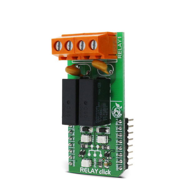
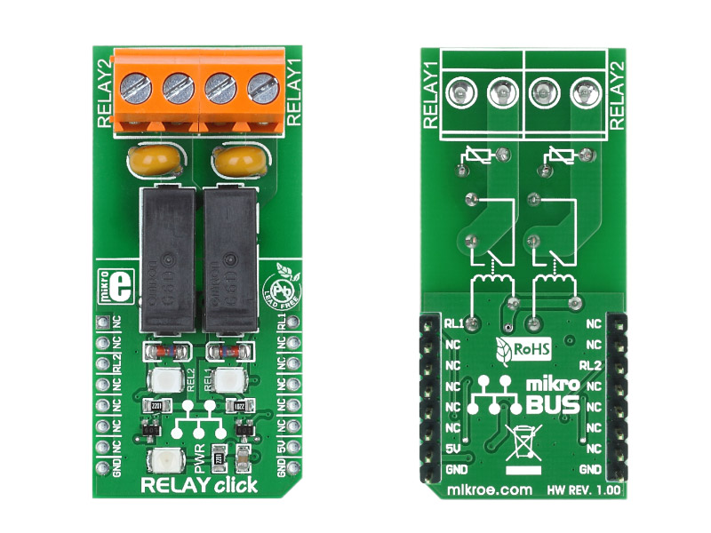
Relay click is a dual relay Click board, which can be operated by the host MCU. This Click board offers an elegant and easy solution for controlling a wide range of high power applications.

No Abuse Reported

Do you want to subscribe in order to receive notifications regarding "Relay click" changes.

Do you want to unsubscribe in order to stop receiving notifications regarding "Relay click" changes.

Do you want to report abuse regarding "Relay click".

  • mikroSDK Library 2.0.0.0
  • Comments (0)
DOWNLOAD LINK RELATED COMPILER CONTAINS
mikroBasic PRO for ARM
  • lib
  • src
  • exa
  • hlp
  • hex
  • sch
  • pcb
  • doc
mikroBasic PRO for AVR
  • lib
  • src
  • exa
  • hlp
  • hex
  • sch
  • pcb
  • doc
mikroBasic PRO for dsPIC30/33 & PIC24
  • lib
  • src
  • exa
  • hlp
  • hex
  • sch
  • pcb
  • doc
mikroBasic PRO for FT90x
  • lib
  • src
  • exa
  • hlp
  • hex
  • sch
  • pcb
  • doc
mikroBasic PRO for PIC
  • lib
  • src
  • exa
  • hlp
  • hex
  • sch
  • pcb
  • doc
mikroBasic PRO for PIC32
  • lib
  • src
  • exa
  • hlp
  • hex
  • sch
  • pcb
  • doc
mikroC PRO for ARM
  • lib
  • src
  • exa
  • hlp
  • hex
  • sch
  • pcb
  • doc
mikroC PRO for AVR
  • lib
  • src
  • exa
  • hlp
  • hex
  • sch
  • pcb
  • doc
mikroC PRO for dsPIC30/33 & PIC24
  • lib
  • src
  • exa
  • hlp
  • hex
  • sch
  • pcb
  • doc
mikroC PRO for FT90x
  • lib
  • src
  • exa
  • hlp
  • hex
  • sch
  • pcb
  • doc
mikroC PRO for PIC
  • lib
  • src
  • exa
  • hlp
  • hex
  • sch
  • pcb
  • doc
mikroC PRO for PIC32
  • lib
  • src
  • exa
  • hlp
  • hex
  • sch
  • pcb
  • doc
mikroPascal PRO for ARM
  • lib
  • src
  • exa
  • hlp
  • hex
  • sch
  • pcb
  • doc
mikroPascal PRO for AVR
  • lib
  • src
  • exa
  • hlp
  • hex
  • sch
  • pcb
  • doc
mikroPascal PRO for dsPIC30/33 & PIC24
  • lib
  • src
  • exa
  • hlp
  • hex
  • sch
  • pcb
  • doc
mikroPascal PRO for FT90x
  • lib
  • src
  • exa
  • hlp
  • hex
  • sch
  • pcb
  • doc
mikroPascal PRO for PIC
  • lib
  • src
  • exa
  • hlp
  • hex
  • sch
  • pcb
  • doc
mikroPascal PRO for PIC32
  • lib
  • src
  • exa
  • hlp
  • hex
  • sch
  • pcb
  • doc

mikroSDK Library Blog

RELAY  click

RELAY click

Native view of the RELAY click board.

View full image
RELAY  click

RELAY click

Front and back view of the RELAY click board

View full image

Library Description

The library offers an option to control the state of relays.

Key functions:

void relay_relay2Control( uint8_t pinState ) - Controls the Relay 2 pin.

void relay_relay1Control( uint8_t pinState ) - Controls the Relay 1 pin.

Examples Description:

The application is composed of three sections:

  • System Initialization - Sets pin directions.
  • Application Initialization - Initializes driver.
  • Application Task - Turns relays on and off.
void applicationTask()
{
relay_relay2Control ( 1 );
relay_relay1Control( 1 );
mikrobus_logWrite("Relays turned on", _LOG_LINE);

Delay_ms(1000);

relay_relay2Control ( 0 );
relay_relay1Control( 0 );
mikrobus_logWrite("Relays turned off", _LOG_LINE);

Delay_ms(1000);
}

Other mikroE Libraries used in the example:

  • UART

Additional notes and information

Depending on the development board you are using, you may need USB UART click,  USB UART 2 click or RS232 click to connect to your PC, for development systems with no UART to USB interface available on the board. The terminal available in all MikroElektronika compilers, or any other terminal application of your choice, can be used to read the message.

ALSO FROM THIS AUTHOR

I2C to CAN Click

0

I2C to CAN Click is a compact add-on board that contains I2C to CAN-physical transceiver, which extends a single-master I2C bus through harsh or noisy environments. This board features the LT3960, a robust high-speed transceiver that extends a single-master I2C bus up to 400kbps using the CAN-physical layer from Analog Devices. One LT3960 from SCL and SDA I2C lines creates equivalent differential buses (CAN) on two twisted pairs, while the second LT3960 recreates the I2C bus locally for any slave I2C devices on the other end of the twisted pairs. A built-in 3.3V LDO powers both the I2C and CAN lines from a single input supply from 4V to 60V. This Click board™ is suitable for industrial and automotive networking, remote sensor applications, and more.

[Learn More]

Cap Touch Click

0

Cap Touch Click is a capacitive touch sensing button, integrated on a Click board. It can be activated by touch.

[Learn More]

IR Sense 5 Click

0

IR Sense 5 Click is a compact add-on board designed for accurate, non-contact surface temperature measurement. This board features the ZTP-148SRC1, a thermopile IR sensor from Amphenol, with a measurement range from -20 to +100°C, an active area of 0.7x0.7mm², and a typical field of view of 85 degrees. The board also integrates an OPA2365AIDR OpAmp for signal amplification and an MCP3221 analog-to-digital converter for digitizing the output. Additional features include output offset selection and test points for signal monitoring.

[Learn More]