TOP Contributors

  1. MIKROE (2784 codes)
  2. Alcides Ramos (405 codes)
  3. Shawon Shahryiar (307 codes)
  4. jm_palomino (133 codes)
  5. Bugz Bensce (97 codes)
  6. S P (73 codes)
  7. dany (71 codes)
  8. MikroBUS.NET Team (35 codes)
  9. NART SCHINACKOW (34 codes)
  10. Armstrong Subero (27 codes)

Most Downloaded

  1. Timer Calculator (141319 times)
  2. FAT32 Library (74154 times)
  3. Network Ethernet Library (58737 times)
  4. USB Device Library (48834 times)
  5. Network WiFi Library (44544 times)
  6. FT800 Library (44120 times)
  7. GSM click (30857 times)
  8. mikroSDK (29699 times)
  9. PID Library (27359 times)
  10. microSD click (27273 times)
Libstock prefers package manager

Package Manager

We strongly encourage users to use Package manager for sharing their code on Libstock website, because it boosts your efficiency and leaves the end user with no room for error. [more info]

< Back
mikroSDK Library

PWR Meter 2 click

Rating:

5

Author: MIKROE

Last Updated: 2018-09-27

Package Version: 1.0.0.0

mikroSDK Library: 1.0.0.0

Category: Measurements

Downloaded: 4833 times

Not followed.

License: MIT license  

PWR Meter 2 click is a compact and accurate power monitoring Click board, capable of measuring and monitoring voltage up to 24V and current up to 5A.

No Abuse Reported

Do you want to subscribe in order to receive notifications regarding "PWR Meter 2 click" changes.

Do you want to unsubscribe in order to stop receiving notifications regarding "PWR Meter 2 click" changes.

Do you want to report abuse regarding "PWR Meter 2 click".
  • mikroSDK Library 2.0.0.0
  • Comments (0)
DOWNLOAD LINK RELATED COMPILER CONTAINS
mikroBasic PRO for ARM
  • lib
  • src
  • exa
  • hlp
  • hex
  • sch
  • pcb
  • doc
mikroBasic PRO for AVR
  • lib
  • src
  • exa
  • hlp
  • hex
  • sch
  • pcb
  • doc
mikroBasic PRO for dsPIC30/33 & PIC24
  • lib
  • src
  • exa
  • hlp
  • hex
  • sch
  • pcb
  • doc
mikroBasic PRO for FT90x
  • lib
  • src
  • exa
  • hlp
  • hex
  • sch
  • pcb
  • doc
mikroBasic PRO for PIC
  • lib
  • src
  • exa
  • hlp
  • hex
  • sch
  • pcb
  • doc
mikroBasic PRO for PIC32
  • lib
  • src
  • exa
  • hlp
  • hex
  • sch
  • pcb
  • doc
mikroC PRO for ARM
  • lib
  • src
  • exa
  • hlp
  • hex
  • sch
  • pcb
  • doc
mikroC PRO for AVR
  • lib
  • src
  • exa
  • hlp
  • hex
  • sch
  • pcb
  • doc
mikroC PRO for dsPIC30/33 & PIC24
  • lib
  • src
  • exa
  • hlp
  • hex
  • sch
  • pcb
  • doc
mikroC PRO for FT90x
  • lib
  • src
  • exa
  • hlp
  • hex
  • sch
  • pcb
  • doc
mikroC PRO for PIC
  • lib
  • src
  • exa
  • hlp
  • hex
  • sch
  • pcb
  • doc
mikroC PRO for PIC32
  • lib
  • src
  • exa
  • hlp
  • hex
  • sch
  • pcb
  • doc
mikroPascal PRO for ARM
  • lib
  • src
  • exa
  • hlp
  • hex
  • sch
  • pcb
  • doc
mikroPascal PRO for AVR
  • lib
  • src
  • exa
  • hlp
  • hex
  • sch
  • pcb
  • doc
mikroPascal PRO for dsPIC30/33 & PIC24
  • lib
  • src
  • exa
  • hlp
  • hex
  • sch
  • pcb
  • doc
mikroPascal PRO for FT90x
  • lib
  • src
  • exa
  • hlp
  • hex
  • sch
  • pcb
  • doc
mikroPascal PRO for PIC
  • lib
  • src
  • exa
  • hlp
  • hex
  • sch
  • pcb
  • doc
mikroPascal PRO for PIC32
  • lib
  • src
  • exa
  • hlp
  • hex
  • sch
  • pcb
  • doc

mikroSDK Library Blog

PWR Meter 2 click

PWR Meter 2 click

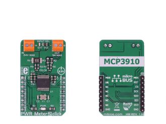
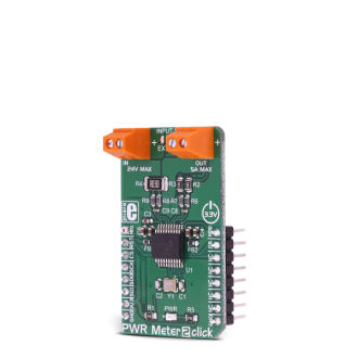
Native view of the PWR Meter 2 click board.

View full image
PWR Meter 2 click

PWR Meter 2 click

Front and back view of the PWR Meter 2 click board.

View full image

Library Description

Library can communicate with the device via SPI driver by writting to the registers and reading from the registers. Library offers a choice to measure output voltage and current, depending on the input voltage supply, and can measure power by calculating this two data values. Library also can check the output state from modulator for both channels. The data resolution can be changed to 16, 24, and 32-bit. For more details check documentation.

Key functions:

  • uint8_t pwrmeter2_writeReg( uint8_t register_address, uint32_t transfer_data ) - Function writes 24-bit data to the register.
  • uint8_t pwrmeter2_readReg( uint8_t register_address, uint32_t *dataOut, uint8_t nData ) - Function reads the desired number of 24-bit data from the register/registers.
  • uint8_t pwrmeter2_readConvData( uint32_t *dataCH0, uint32_t *dataCH1 ) - Function reads the converted data from both channels when conversion is finished.
  • void pwrmeter2_getData( int32_t *voltageData, int32_t *currentData, int32_t *powerData ) - Function gets the calculated voltage(mV), current(mA) and power(mW) data.

Example description

The application is composed of three sections :

System Initialization - Initializes peripherals and pins.
Application Initialization - Initializes SPI driver and performs the hardware reset of the device.
Also performs the device configuration and gain calibration for both channels, for the properly working.
Application Task - (code snippet) - Gets calculated voltage, current and power data every 500 miliseconds
and shows results on UART.

void applicationTask()
{
 pwrmeter2_getData( &voltageRes, ¤tRes, &powerRes );

 LongToStr( voltageRes, text );
 mikrobus_logWrite( "U = ", _LOG_TEXT );
 mikrobus_logWrite( text, _LOG_TEXT );
 mikrobus_logWrite( " mV", _LOG_LINE );

 LongToStr( currentRes, text );
 mikrobus_logWrite( "I = ", _LOG_TEXT );
 mikrobus_logWrite( text, _LOG_TEXT );
 mikrobus_logWrite( " mA", _LOG_LINE );

 LongToStr( powerRes, text );
 mikrobus_logWrite( "P = ", _LOG_TEXT );
 mikrobus_logWrite( text, _LOG_TEXT );
 mikrobus_logWrite( " mW", _LOG_LINE );
 mikrobus_logWrite( "", _LOG_LINE );

 Delay_ms( 500 );
}


Other MikroElektronika libraries used in the example:

  • SPI
  • UART
  • Conversions

Additional notes and information

Depending on the development board you are using, you may need USB UART clickUSB UART 2 click or RS232 click to connect to your PC, for development systems with no UART to USB interface available on the board. The terminal available in all MikroElektronika compilers, or any other terminal application of your choice, can be used to read the message.

ALSO FROM THIS AUTHOR

DIGI POT 7 Click

0

DIGI POT 7 Click is a compact add-on board used as a digitally controlled potentiometer. This board features the AD5175, a single-channel 1024-position digital rheostat with less than ±1% end-to-end resistor tolerance error and 50-time programmable wiper memory from Analog Devices. This I2C configurable IC is designed to operate as a variable resistor for analog signals, within the voltage range of single-supply operation at 2.7 V to 5.5 V.

[Learn More]

GPS2 click - Example

0

Simple example which demonstrates usage of the GPS2 Click board with QUECTEL L30 GPS module. It displays a map of the world on the TFT and shows the location of the GPS module on it.

[Learn More]

Stepper Click

0

Stepper Click is a complete solution for driving bipolar stepper motors with full/half and micro-steps. It features the A3967 IC from Allegro Microsystems with proprietary Satlington™ sink drivers on its outputs, which ensure high efficiency and reliable operation of the internal H-Bridges. This IC has the integrated translation section, used to simplify the control: using simple step control inputs from the host MCU, the stepper motor can be driven in both directions, with the predetermined step sizes. In addition, the output current is regulated allowing for noiseless operation of the stepper motor, with no resonance and ringing typically observed at unregulated stepper driver designs.

[Learn More]