TOP Contributors

  1. MIKROE (2652 codes)
  2. Alcides Ramos (351 codes)
  3. Shawon Shahryiar (307 codes)
  4. jm_palomino (112 codes)
  5. Chisanga Mumba (90 codes)
  6. S P (73 codes)
  7. dany (71 codes)
  8. MikroBUS.NET Team (35 codes)
  9. NART SCHINACKOW (34 codes)
  10. Armstrong Subero (27 codes)

Most Downloaded

  1. Timer Calculator (136632 times)
  2. FAT32 Library (69839 times)
  3. Network Ethernet Library (55891 times)
  4. USB Device Library (46227 times)
  5. Network WiFi Library (41863 times)
  6. FT800 Library (41084 times)
  7. GSM click (28945 times)
  8. PID Library (26402 times)
  9. mikroSDK (26317 times)
  10. microSD click (25328 times)
Libstock prefers package manager

Package Manager

We strongly encourage users to use Package manager for sharing their code on Libstock website, because it boosts your efficiency and leaves the end user with no room for error. [more info]

< Back
mikroSDK Library

PWR Meter 2 click

Rating:

5

Author: MIKROE

Last Updated: 2018-09-27

Package Version: 1.0.0.0

mikroSDK Library: 1.0.0.0

Category: Measurements

Downloaded: 3659 times

Not followed.

License: MIT license  

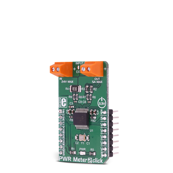
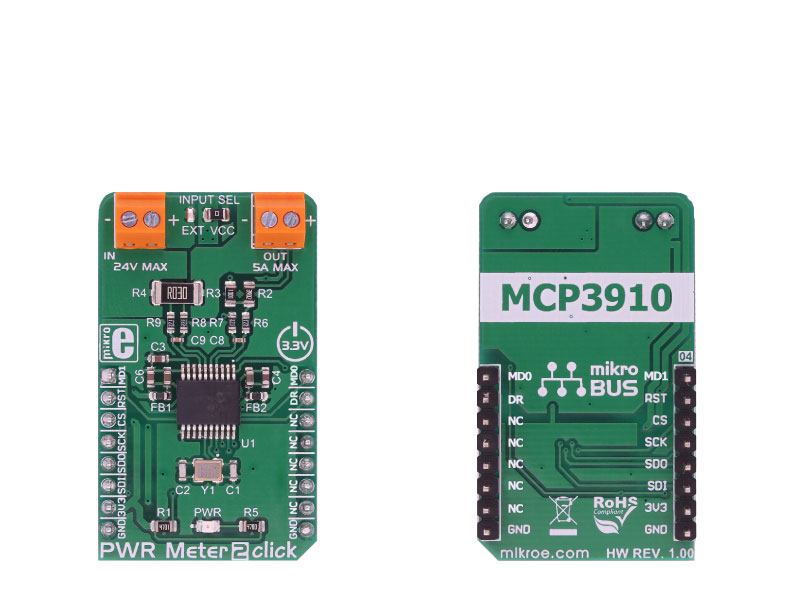
PWR Meter 2 click is a compact and accurate power monitoring Click board, capable of measuring and monitoring voltage up to 24V and current up to 5A.

No Abuse Reported

Do you want to subscribe in order to receive notifications regarding "PWR Meter 2 click" changes.

Do you want to unsubscribe in order to stop receiving notifications regarding "PWR Meter 2 click" changes.

Do you want to report abuse regarding "PWR Meter 2 click".

  • mikroSDK Library 2.0.0.0
  • Comments (0)
DOWNLOAD LINK RELATED COMPILER CONTAINS
mikroBasic PRO for ARM
  • lib
  • src
  • exa
  • hlp
  • hex
  • sch
  • pcb
  • doc
mikroBasic PRO for AVR
  • lib
  • src
  • exa
  • hlp
  • hex
  • sch
  • pcb
  • doc
mikroBasic PRO for dsPIC30/33 & PIC24
  • lib
  • src
  • exa
  • hlp
  • hex
  • sch
  • pcb
  • doc
mikroBasic PRO for FT90x
  • lib
  • src
  • exa
  • hlp
  • hex
  • sch
  • pcb
  • doc
mikroBasic PRO for PIC
  • lib
  • src
  • exa
  • hlp
  • hex
  • sch
  • pcb
  • doc
mikroBasic PRO for PIC32
  • lib
  • src
  • exa
  • hlp
  • hex
  • sch
  • pcb
  • doc
mikroC PRO for ARM
  • lib
  • src
  • exa
  • hlp
  • hex
  • sch
  • pcb
  • doc
mikroC PRO for AVR
  • lib
  • src
  • exa
  • hlp
  • hex
  • sch
  • pcb
  • doc
mikroC PRO for dsPIC30/33 & PIC24
  • lib
  • src
  • exa
  • hlp
  • hex
  • sch
  • pcb
  • doc
mikroC PRO for FT90x
  • lib
  • src
  • exa
  • hlp
  • hex
  • sch
  • pcb
  • doc
mikroC PRO for PIC
  • lib
  • src
  • exa
  • hlp
  • hex
  • sch
  • pcb
  • doc
mikroC PRO for PIC32
  • lib
  • src
  • exa
  • hlp
  • hex
  • sch
  • pcb
  • doc
mikroPascal PRO for ARM
  • lib
  • src
  • exa
  • hlp
  • hex
  • sch
  • pcb
  • doc
mikroPascal PRO for AVR
  • lib
  • src
  • exa
  • hlp
  • hex
  • sch
  • pcb
  • doc
mikroPascal PRO for dsPIC30/33 & PIC24
  • lib
  • src
  • exa
  • hlp
  • hex
  • sch
  • pcb
  • doc
mikroPascal PRO for FT90x
  • lib
  • src
  • exa
  • hlp
  • hex
  • sch
  • pcb
  • doc
mikroPascal PRO for PIC
  • lib
  • src
  • exa
  • hlp
  • hex
  • sch
  • pcb
  • doc
mikroPascal PRO for PIC32
  • lib
  • src
  • exa
  • hlp
  • hex
  • sch
  • pcb
  • doc

mikroSDK Library Blog

PWR Meter 2 click

PWR Meter 2 click

Native view of the PWR Meter 2 click board.

View full image
PWR Meter 2 click

PWR Meter 2 click

Front and back view of the PWR Meter 2 click board.

View full image

Library Description

Library can communicate with the device via SPI driver by writting to the registers and reading from the registers. Library offers a choice to measure output voltage and current, depending on the input voltage supply, and can measure power by calculating this two data values. Library also can check the output state from modulator for both channels. The data resolution can be changed to 16, 24, and 32-bit. For more details check documentation.

Key functions:

  • uint8_t pwrmeter2_writeReg( uint8_t register_address, uint32_t transfer_data ) - Function writes 24-bit data to the register.
  • uint8_t pwrmeter2_readReg( uint8_t register_address, uint32_t *dataOut, uint8_t nData ) - Function reads the desired number of 24-bit data from the register/registers.
  • uint8_t pwrmeter2_readConvData( uint32_t *dataCH0, uint32_t *dataCH1 ) - Function reads the converted data from both channels when conversion is finished.
  • void pwrmeter2_getData( int32_t *voltageData, int32_t *currentData, int32_t *powerData ) - Function gets the calculated voltage(mV), current(mA) and power(mW) data.

Example description

The application is composed of three sections :

System Initialization - Initializes peripherals and pins.
Application Initialization - Initializes SPI driver and performs the hardware reset of the device.
Also performs the device configuration and gain calibration for both channels, for the properly working.
Application Task - (code snippet) - Gets calculated voltage, current and power data every 500 miliseconds
and shows results on UART.

void applicationTask()
{
 pwrmeter2_getData( &voltageRes, ¤tRes, &powerRes );

 LongToStr( voltageRes, text );
 mikrobus_logWrite( "U = ", _LOG_TEXT );
 mikrobus_logWrite( text, _LOG_TEXT );
 mikrobus_logWrite( " mV", _LOG_LINE );

 LongToStr( currentRes, text );
 mikrobus_logWrite( "I = ", _LOG_TEXT );
 mikrobus_logWrite( text, _LOG_TEXT );
 mikrobus_logWrite( " mA", _LOG_LINE );

 LongToStr( powerRes, text );
 mikrobus_logWrite( "P = ", _LOG_TEXT );
 mikrobus_logWrite( text, _LOG_TEXT );
 mikrobus_logWrite( " mW", _LOG_LINE );
 mikrobus_logWrite( "", _LOG_LINE );

 Delay_ms( 500 );
}


Other MikroElektronika libraries used in the example:

  • SPI
  • UART
  • Conversions

Additional notes and information

Depending on the development board you are using, you may need USB UART clickUSB UART 2 click or RS232 click to connect to your PC, for development systems with no UART to USB interface available on the board. The terminal available in all MikroElektronika compilers, or any other terminal application of your choice, can be used to read the message.

ALSO FROM THIS AUTHOR

Smart Buck 3 click

0

Smart Buck 3 Click is a compact add-on board that contains a high-frequency synchronous step-down DC-DC converter. This board features the TPS62366A, a processor supply with I2C compatible interface and a remote sense from Texas Instruments. As input, it uses voltages in the range of 2.5V up to 5.5V, including support for common battery technologies. As output, the converter can scale voltage from 0.5V up to 1.77V in 10mV steps, retaining up to 2.5A peak output current, operating at 2.5MHz of the typical switching frequency.

[Learn More]

Barcode click

5

Barcode click is a very fast and agile barcode scanner on a click board, which is compliant with a wide range of different 1D and 2D barcode protocols.

[Learn More]

mikromedia for dsPIC33EP - Examples

0

Set of examples for mikromedia for dsPIC33EP.. Provided examples demonstrate working with mikromedia's various features and modules:

- Accelerometer
- MMC SD card
- MP3
- Serial Flash
- TFT
- Touch Panel
- USB

[Learn More]