TOP Contributors

  1. MIKROE (2784 codes)
  2. Alcides Ramos (405 codes)
  3. Shawon Shahryiar (307 codes)
  4. jm_palomino (133 codes)
  5. Bugz Bensce (97 codes)
  6. S P (73 codes)
  7. dany (71 codes)
  8. MikroBUS.NET Team (35 codes)
  9. NART SCHINACKOW (34 codes)
  10. Armstrong Subero (27 codes)

Most Downloaded

  1. Timer Calculator (141825 times)
  2. FAT32 Library (74956 times)
  3. Network Ethernet Library (59317 times)
  4. USB Device Library (49308 times)
  5. Network WiFi Library (45108 times)
  6. FT800 Library (44676 times)
  7. GSM click (31287 times)
  8. mikroSDK (30215 times)
  9. microSD click (27664 times)
  10. PID Library (27564 times)
Libstock prefers package manager

Package Manager

We strongly encourage users to use Package manager for sharing their code on Libstock website, because it boosts your efficiency and leaves the end user with no room for error. [more info]

< Back
mikroSDK Library

Hz to V 2 click

Rating:

5

Author: MIKROE

Last Updated: 2018-08-15

Package Version: 1.0.0.0

mikroSDK Library: 1.0.0.0

Category: Measurements

Downloaded: 5527 times

Not followed.

License: MIT license  

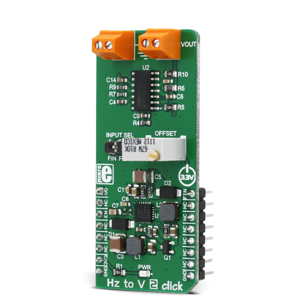
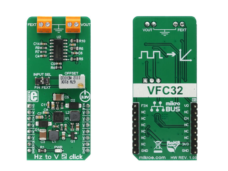
HZ to V 2 click is a device that can convert input frequency of the signal with virtually any wave shape to a DC voltage output, with a level proportional to the input frequency.

No Abuse Reported

Do you want to subscribe in order to receive notifications regarding "Hz to V 2 click" changes.

Do you want to unsubscribe in order to stop receiving notifications regarding "Hz to V 2 click" changes.

Do you want to report abuse regarding "Hz to V 2 click".

  • mikroSDK Library 2.0.0.0
  • Comments (0)
DOWNLOAD LINK RELATED COMPILER CONTAINS
mikroBasic PRO for ARM
  • lib
  • src
  • exa
  • hlp
  • hex
  • sch
  • pcb
  • doc
mikroBasic PRO for AVR
  • lib
  • src
  • exa
  • hlp
  • hex
  • sch
  • pcb
  • doc
mikroBasic PRO for dsPIC30/33 & PIC24
  • lib
  • src
  • exa
  • hlp
  • hex
  • sch
  • pcb
  • doc
mikroBasic PRO for FT90x
  • lib
  • src
  • exa
  • hlp
  • hex
  • sch
  • pcb
  • doc
mikroBasic PRO for PIC
  • lib
  • src
  • exa
  • hlp
  • hex
  • sch
  • pcb
  • doc
mikroBasic PRO for PIC32
  • lib
  • src
  • exa
  • hlp
  • hex
  • sch
  • pcb
  • doc
mikroC PRO for ARM
  • lib
  • src
  • exa
  • hlp
  • hex
  • sch
  • pcb
  • doc
mikroC PRO for AVR
  • lib
  • src
  • exa
  • hlp
  • hex
  • sch
  • pcb
  • doc
mikroC PRO for dsPIC30/33 & PIC24
  • lib
  • src
  • exa
  • hlp
  • hex
  • sch
  • pcb
  • doc
mikroC PRO for FT90x
  • lib
  • src
  • exa
  • hlp
  • hex
  • sch
  • pcb
  • doc
mikroC PRO for PIC
  • lib
  • src
  • exa
  • hlp
  • hex
  • sch
  • pcb
  • doc
mikroC PRO for PIC32
  • lib
  • src
  • exa
  • hlp
  • hex
  • sch
  • pcb
  • doc
mikroPascal PRO for ARM
  • lib
  • src
  • exa
  • hlp
  • hex
  • sch
  • pcb
  • doc
mikroPascal PRO for AVR
  • lib
  • src
  • exa
  • hlp
  • hex
  • sch
  • pcb
  • doc
mikroPascal PRO for dsPIC30/33 & PIC24
  • lib
  • src
  • exa
  • hlp
  • hex
  • sch
  • pcb
  • doc
mikroPascal PRO for FT90x
  • lib
  • src
  • exa
  • hlp
  • hex
  • sch
  • pcb
  • doc
mikroPascal PRO for PIC
  • lib
  • src
  • exa
  • hlp
  • hex
  • sch
  • pcb
  • doc
mikroPascal PRO for PIC32
  • lib
  • src
  • exa
  • hlp
  • hex
  • sch
  • pcb
  • doc

mikroSDK Library Blog

Hz to V 2 click

Hz to V 2 click

Native view of the Hz to V 2 click board.

View full image
Hz to V 2 click

Hz to V 2 click

Front and back view of the Hz to V 2 click board.

View full image

Library Description

Library provides generic functions for working with the click board.

Key functions :


  • void hztov2_enPin(uint8_t pinState) - Function for enabling the click board.
  • void hztov2_adcInit() - Prepare the ADC for voltage readings.
  • float hztov2_adcRead() - Read the voltages and return the return the float voltage value.

Example description

The application is composed of three sections:

  • System Initialization - Initializes GPIO and UART structures.
  • Application Initialization - Power on the click board and initializeS the ADC.
  • Application Task - Voltage reading is done from the analog pin and the conversion result is converted and output via the UART output.
void applicationTask()
{
 float voltage;
 char txt[20];

 voltage = hztov2_adcRead();
 if(voltage<0.99)
 {
 voltage = voltage * 1000.0;
 FloatToStr(voltage,txt);
 txt[5] = 'm';
 txt[6] = 'V';
 txt[7] = 0;
 }
 else
 {
 FloatToStr(voltage,txt);
 txt[5] = ' ';
 txt[6] = 'V';
 txt[7] = 0;
 }

 mikrobus_logWrite(txt,_LOG_LINE);
 Delay_ms(100);
}

Other mikroE Libraries used in the example:

  • UART Library
  • Conversions Library
  • C_String Library
  • ADC Library

Additional notes and information

Depending on the development board you are using, you may need USB UART clickUSB UART 2 click or RS232 click to connect to your PC, for development systems with no UART to USB interface available on the board. The terminal available in all MikroElektronika compilers, or any other terminal application of your choice, can be used to read the message.

ALSO FROM THIS AUTHOR

Power Monitor Click

0

Power Monitor Click is a compact add-on board that represents an ultra-precise power monitoring solution. This board features the INA228, a digital power monitor with a 20-bit delta-sigma ADC specifically designed for current-sensing applications from Texas Instruments. The INA228 reports current, bus voltage, temperature, power, energy, and charge accumulation while employing a precision ±0.5 % integrated oscillator, all while performing the needed calculations in the background. It can measure a full-scale differential input of ±163.84mV or ±40.96mV across a resistive shunt sense element, with common-mode voltage support up to +85V. This Click board™ is suitable for current-sensing applications in DC-DC converters, power inverters, telecom equipment, industrial measurements, and many more.

[Learn More]

Clock Gen 6 Click

0

Clock Gen 6 Click is a compact add-on board representing a digital oscillator solution. This board features the MIC1557, an IttyBitty CMOS RC oscillator designed to provide rail-to-rail pulses for precise time delay or frequency generation from Microchip Technology. The MIC1557 has a single threshold and trigger connection, internally connected, for astable (oscillator) operation only. It also has an enable/reset control signal routed to the RST pin of the mikroBUS™ socket, which controls the bias supply to the oscillator’s internal circuitry and optimizes power consumption used for oscillator power ON/OFF purposes. In addition, it provides the ability to select the desired frequency programmed via a digital potentiometer, the MAX5401.

[Learn More]

Relay 2 click

5

Relay 2 click carries two LCA717 single-pole, OptoMOS® solid state relays and two screw terminals for connecting the wiring. They are controlled by the microcontroller through RL1 and RL2 pins, which are in place of default mikroBUS AN and PWM pins.

[Learn More]