TOP Contributors

  1. MIKROE (2784 codes)
  2. Alcides Ramos (403 codes)
  3. Shawon Shahryiar (307 codes)
  4. jm_palomino (132 codes)
  5. Bugz Bensce (97 codes)
  6. S P (73 codes)
  7. dany (71 codes)
  8. MikroBUS.NET Team (35 codes)
  9. NART SCHINACKOW (34 codes)
  10. Armstrong Subero (27 codes)

Most Downloaded

  1. Timer Calculator (140969 times)
  2. FAT32 Library (73516 times)
  3. Network Ethernet Library (58322 times)
  4. USB Device Library (48510 times)
  5. Network WiFi Library (44134 times)
  6. FT800 Library (43689 times)
  7. GSM click (30547 times)
  8. mikroSDK (29295 times)
  9. PID Library (27220 times)
  10. microSD click (26931 times)
Libstock prefers package manager

Package Manager

We strongly encourage users to use Package manager for sharing their code on Libstock website, because it boosts your efficiency and leaves the end user with no room for error. [more info]

< Back
mikroSDK Library

BUCK 7 click

Rating:

5

Author: MIKROE

Last Updated: 2018-07-12

Package Version: 1.0.0.0

mikroSDK Library: 1.0.0.0

Category: Buck

Downloaded: 4630 times

Not followed.

License: MIT license  

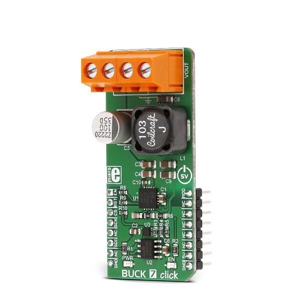
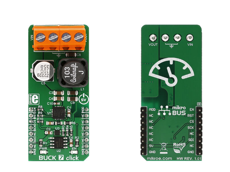
Buck 7 click is a high-efficiency buck (step-down) DC-DC converter, which can provide digitally adjusted step-down voltage on its output while delivering up to 3.5A of current.

No Abuse Reported

Do you want to subscribe in order to receive notifications regarding "BUCK 7 click" changes.

Do you want to unsubscribe in order to stop receiving notifications regarding "BUCK 7 click" changes.

Do you want to report abuse regarding "BUCK 7 click".

  • mikroSDK Library 2.0.0.0
  • Comments (0)
DOWNLOAD LINK RELATED COMPILER CONTAINS
mikroBasic PRO for ARM
  • lib
  • src
  • exa
  • hlp
  • hex
  • sch
  • pcb
  • doc
mikroBasic PRO for AVR
  • lib
  • src
  • exa
  • hlp
  • hex
  • sch
  • pcb
  • doc
mikroBasic PRO for dsPIC30/33 & PIC24
  • lib
  • src
  • exa
  • hlp
  • hex
  • sch
  • pcb
  • doc
mikroBasic PRO for FT90x
  • lib
  • src
  • exa
  • hlp
  • hex
  • sch
  • pcb
  • doc
mikroBasic PRO for PIC
  • lib
  • src
  • exa
  • hlp
  • hex
  • sch
  • pcb
  • doc
mikroBasic PRO for PIC32
  • lib
  • src
  • exa
  • hlp
  • hex
  • sch
  • pcb
  • doc
mikroC PRO for ARM
  • lib
  • src
  • exa
  • hlp
  • hex
  • sch
  • pcb
  • doc
mikroC PRO for AVR
  • lib
  • src
  • exa
  • hlp
  • hex
  • sch
  • pcb
  • doc
mikroC PRO for dsPIC30/33 & PIC24
  • lib
  • src
  • exa
  • hlp
  • hex
  • sch
  • pcb
  • doc
mikroC PRO for FT90x
  • lib
  • src
  • exa
  • hlp
  • hex
  • sch
  • pcb
  • doc
mikroC PRO for PIC
  • lib
  • src
  • exa
  • hlp
  • hex
  • sch
  • pcb
  • doc
mikroC PRO for PIC32
  • lib
  • src
  • exa
  • hlp
  • hex
  • sch
  • pcb
  • doc
mikroPascal PRO for ARM
  • lib
  • src
  • exa
  • hlp
  • hex
  • sch
  • pcb
  • doc
mikroPascal PRO for AVR
  • lib
  • src
  • exa
  • hlp
  • hex
  • sch
  • pcb
  • doc
mikroPascal PRO for dsPIC30/33 & PIC24
  • lib
  • src
  • exa
  • hlp
  • hex
  • sch
  • pcb
  • doc
mikroPascal PRO for FT90x
  • lib
  • src
  • exa
  • hlp
  • hex
  • sch
  • pcb
  • doc
mikroPascal PRO for PIC
  • lib
  • src
  • exa
  • hlp
  • hex
  • sch
  • pcb
  • doc
mikroPascal PRO for PIC32
  • lib
  • src
  • exa
  • hlp
  • hex
  • sch
  • pcb
  • doc

mikroSDK Library Blog

Buck 7 click

Buck 7 click

Native view of the Buck 7 click board.

View full image
Buck 7 click

Buck 7 click

Front and back view of the Buck 7 click board.

View full image

Library Description

The library initializes and defines the SPI bus driver. The library includes function for sets output voltage and functions for enable chip. The user also has the function for sets work mode.

Key functions :

void buck7_setOutputVoltage(uint16_t voltage) - Function for set output voltage
void buck7_enable() - Function for enable chip
void buck7_setMode(uint8_t mode) - Function for set chip mode

Example description

The application is composed of three sections:

  • System Initialization - Initializes SPI module and set AN,RST,CS and PWM pin as OUTPUT
  • Application Initialization - Initializes Driver init, enable chip and set mode
  • Application Task - (code snippet) - Sets output voltage to 5V, 10V, 15V, 20V, 25V every 3 seconds. It is necessary to set the input voltage on 2.7V + maximum output voltage.
void applicationTask()
{
 buck7_setOutputVoltage( _BUCK7_OUT_VOLTAGE_5V );
 Delay_ms( 3000 );
 buck7_setOutputVoltage( _BUCK7_OUT_VOLTAGE_10V );
 Delay_ms( 3000 );
 buck7_setOutputVoltage( _BUCK7_OUT_VOLTAGE_15V );
 Delay_ms( 3000 );
 buck7_setOutputVoltage( _BUCK7_OUT_VOLTAGE_20V );
 Delay_ms( 3000 );
 buck7_setOutputVoltage( _BUCK7_OUT_VOLTAGE_25V );
 Delay_ms( 3000 );
 buck7_setOutputVoltage( _BUCK7_OUT_VOLTAGE_20V );
 Delay_ms( 3000 );
 buck7_setOutputVoltage( _BUCK7_OUT_VOLTAGE_15V );
 Delay_ms( 3000 );
 buck7_setOutputVoltage( 0x0BB8 ); /* 10 V */
 Delay_ms( 3000 );
}

mikroE Libraries used in the example:

  • SPI

Additional notes and information

Depending on the development board you are using, you may need USB UART clickUSB UART 2 click or RS232 click to connect to your PC, for development systems with no UART to USB interface available on the board. The terminal available in all MikroElektronika compilers, or any other terminal application of your choice, can be used to read the message.

ALSO FROM THIS AUTHOR

Fiber Opt Click

0

Fiber Opt Click is a compact and easy solution for adding fiber-optic communication to your design. It features IF-D91 fiber-optic photodiode, IF-E97 fiber-optic LED diode as well as two operational amplifiers.

[Learn More]

Step Down 10 Click

0

Step Down 10 Click is a compact add-on board that converts higher voltages into a lower voltage level. This board features the TPSM63610, a high-density synchronous buck DC/DC power module with enhanced HotRodTM from Texas Instruments.

[Learn More]

ECG 7 Click

0

ECG 7 Click is a compact add-on board that records the heart's electrical activity. This board features the MCP6N16, a single zero-drift instrumentation amplifier with selectable gain from Microchip. In addition to the jack connector provided for connecting the cable with ECG electrodes, this Click boardâ„¢ offers the possibility of connecting electrodes through screw terminals or an onboard header if the electrode connection does not match the jack connector. Besides, the user is allowed to process the output signal in analog or digital form.

[Learn More]