TOP Contributors

  1. MIKROE (2784 codes)
  2. Alcides Ramos (405 codes)
  3. Shawon Shahryiar (307 codes)
  4. jm_palomino (133 codes)
  5. Bugz Bensce (97 codes)
  6. S P (73 codes)
  7. dany (71 codes)
  8. MikroBUS.NET Team (35 codes)
  9. NART SCHINACKOW (34 codes)
  10. Armstrong Subero (27 codes)

Most Downloaded

  1. Timer Calculator (141646 times)
  2. FAT32 Library (74666 times)
  3. Network Ethernet Library (59129 times)
  4. USB Device Library (49175 times)
  5. Network WiFi Library (44944 times)
  6. FT800 Library (44469 times)
  7. GSM click (31137 times)
  8. mikroSDK (30049 times)
  9. microSD click (27545 times)
  10. PID Library (27515 times)
Libstock prefers package manager

Package Manager

We strongly encourage users to use Package manager for sharing their code on Libstock website, because it boosts your efficiency and leaves the end user with no room for error. [more info]

< Back
mikroSDK Library

Boost-INV 2 click

Rating:

5

Author: MIKROE

Last Updated: 2018-08-14

Package Version: 1.0.0.0

mikroSDK Library: 1.0.0.0

Category: Boost

Downloaded: 5440 times

Not followed.

License: MIT license  

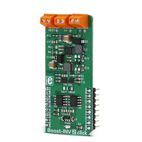
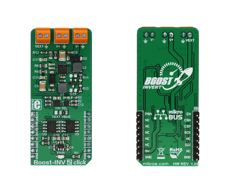
Boost-INV 2 click is a very useful DC/DC voltage converter device, as can output both positive and negative voltage, boosted up to 15V and inverted to -15V, from a single fixed voltage input.

No Abuse Reported

Do you want to subscribe in order to receive notifications regarding "Boost-INV 2 click" changes.

Do you want to unsubscribe in order to stop receiving notifications regarding "Boost-INV 2 click" changes.

Do you want to report abuse regarding "Boost-INV 2 click".

  • mikroSDK Library 2.0.0.0
  • Comments (0)
DOWNLOAD LINK RELATED COMPILER CONTAINS
mikroBasic PRO for ARM
  • lib
  • src
  • exa
  • hlp
  • hex
  • sch
  • pcb
  • doc
mikroBasic PRO for AVR
  • lib
  • src
  • exa
  • hlp
  • hex
  • sch
  • pcb
  • doc
mikroBasic PRO for dsPIC30/33 & PIC24
  • lib
  • src
  • exa
  • hlp
  • hex
  • sch
  • pcb
  • doc
mikroBasic PRO for FT90x
  • lib
  • src
  • exa
  • hlp
  • hex
  • sch
  • pcb
  • doc
mikroBasic PRO for PIC
  • lib
  • src
  • exa
  • hlp
  • hex
  • sch
  • pcb
  • doc
mikroBasic PRO for PIC32
  • lib
  • src
  • exa
  • hlp
  • hex
  • sch
  • pcb
  • doc
mikroC PRO for ARM
  • lib
  • src
  • exa
  • hlp
  • hex
  • sch
  • pcb
  • doc
mikroC PRO for AVR
  • lib
  • src
  • exa
  • hlp
  • hex
  • sch
  • pcb
  • doc
mikroC PRO for dsPIC30/33 & PIC24
  • lib
  • src
  • exa
  • hlp
  • hex
  • sch
  • pcb
  • doc
mikroC PRO for FT90x
  • lib
  • src
  • exa
  • hlp
  • hex
  • sch
  • pcb
  • doc
mikroC PRO for PIC
  • lib
  • src
  • exa
  • hlp
  • hex
  • sch
  • pcb
  • doc
mikroC PRO for PIC32
  • lib
  • src
  • exa
  • hlp
  • hex
  • sch
  • pcb
  • doc
mikroPascal PRO for ARM
  • lib
  • src
  • exa
  • hlp
  • hex
  • sch
  • pcb
  • doc
mikroPascal PRO for AVR
  • lib
  • src
  • exa
  • hlp
  • hex
  • sch
  • pcb
  • doc
mikroPascal PRO for dsPIC30/33 & PIC24
  • lib
  • src
  • exa
  • hlp
  • hex
  • sch
  • pcb
  • doc
mikroPascal PRO for FT90x
  • lib
  • src
  • exa
  • hlp
  • hex
  • sch
  • pcb
  • doc
mikroPascal PRO for PIC
  • lib
  • src
  • exa
  • hlp
  • hex
  • sch
  • pcb
  • doc
mikroPascal PRO for PIC32
  • lib
  • src
  • exa
  • hlp
  • hex
  • sch
  • pcb
  • doc

mikroSDK Library Blog

Boost-INV 2 click

Boost-INV 2 click

Native view of the Boost-INV 2 click board.

View full image
Boost-INV 2 click

Boost-INV 2 click

Front and back view of the Boost-INV 2 click board.

View full image

Library Description

The library initializes and defines SPI drivers along with the driver that gives an option to set desired positive and negative output voltages.

Key functions:

  • void boostinv2_enable() - Functions for enable chip.
  • void boostinv2_setPositiveVoltage( uint16_t voltage ) - Functions for set positive output voltage.
  • void boostinv2_setNegativeVoltage( uint16_t voltage ) - Functions for set negative output voltage.

Example description

The application is composed of three sections:

  • System Initialization - Initializes I2C module and sets RST,AN,CS and PWM pin as OUTPUT
  • Application Initialization - Initializes Driver init and enable chip
  • Application Task - (code snippet) - Changes the positive and negative output voltage. Positive output voltage goes from 5V to 15V with Negative output voltage goes from -5V to -15V
void applicationTask()
{
 /* Positive output voltage */
 boostinv2_setPositiveVoltage( _BOOSTINV2_POS_VOUT_6V );
 Delay_ms( 3000 );
 boostinv2_setPositiveVoltage( _BOOSTINV2_POS_VOUT_8V );
 Delay_ms( 3000 );
 boostinv2_setPositiveVoltage( _BOOSTINV2_POS_VOUT_12V );
 Delay_ms( 3000 );
 boostinv2_setPositiveVoltage( _BOOSTINV2_POS_VOUT_14V );
 Delay_ms( 3000 );
 boostinv2_setPositiveVoltage( _BOOSTINV2_POS_VOUT_12V );
 Delay_ms( 3000 );
 boostinv2_setPositiveVoltage( _BOOSTINV2_POS_VOUT_8V );
 /* Negative output voltage */
 boostinv2_setNegativeVoltage( _BOOSTINV2_NEG_VOUT_5V );
 Delay_ms( 3000 );
 boostinv2_setNegativeVoltage( _BOOSTINV2_NEG_VOUT_7V );
 Delay_ms( 3000 );
 boostinv2_setNegativeVoltage( _BOOSTINV2_NEG_VOUT_13V );
 Delay_ms( 3000 );
 boostinv2_setNegativeVoltage( _BOOSTINV2_NEG_VOUT_7V );
}

Other MikroElektronika libraries used in the example:

  • SPI

Additional notes and information

Depending on the development board you are using, you may need USB UART clickUSB UART 2 click or RS232 click to connect to your PC, for development systems with no UART to USB interface available on the board. The terminal available in all MikroElektronika compilers, or any other terminal application of your choice, can be used to read the message.

ALSO FROM THIS AUTHOR

Step Up Click

0

Step Up Click is a fixed frequency DC-DC step-up (boost) regulator, which can be obtained from any low voltage input - such as NiCd, NiMH or one cell Li-Po/Li-Ion batteries.

[Learn More]

Joystick 2 click

5

Joystick 2 Click is a smart navigation key concept based on SKRHABE010 by Alps, a 4-direction joystick switch with Center-push Function. Alps switches, also known as microswitches, are well renowned for their reliability and endurance.

[Learn More]

FAN 6 click

5

The Fan 6 click is a Click board which features EMC2103, an SMBus compliant fan controller with up to up to 3 external and 1 internal temperature channels. The fan driver can be operated using two methods each with two modes. The methods include an RPM based Fan Speed Control Algorithm and a direct PWM drive setting.

[Learn More]