TOP Contributors

  1. MIKROE (2784 codes)
  2. Alcides Ramos (404 codes)
  3. Shawon Shahryiar (307 codes)
  4. jm_palomino (133 codes)
  5. Bugz Bensce (97 codes)
  6. S P (73 codes)
  7. dany (71 codes)
  8. MikroBUS.NET Team (35 codes)
  9. NART SCHINACKOW (34 codes)
  10. Armstrong Subero (27 codes)

Most Downloaded

  1. Timer Calculator (141111 times)
  2. FAT32 Library (73901 times)
  3. Network Ethernet Library (58554 times)
  4. USB Device Library (48724 times)
  5. Network WiFi Library (44376 times)
  6. FT800 Library (43976 times)
  7. GSM click (30721 times)
  8. mikroSDK (29478 times)
  9. PID Library (27299 times)
  10. microSD click (27102 times)
Libstock prefers package manager

Package Manager

We strongly encourage users to use Package manager for sharing their code on Libstock website, because it boosts your efficiency and leaves the end user with no room for error. [more info]

< Back
mikroSDK Library

Knob G click

Rating:

6

Author: MIKROE

Last Updated: 2018-12-26

Package Version: 1.0.0.0

mikroSDK Library: 1.0.0.0

Category: Rotary encoder

Downloaded: 4458 times

Not followed.

License: MIT license  

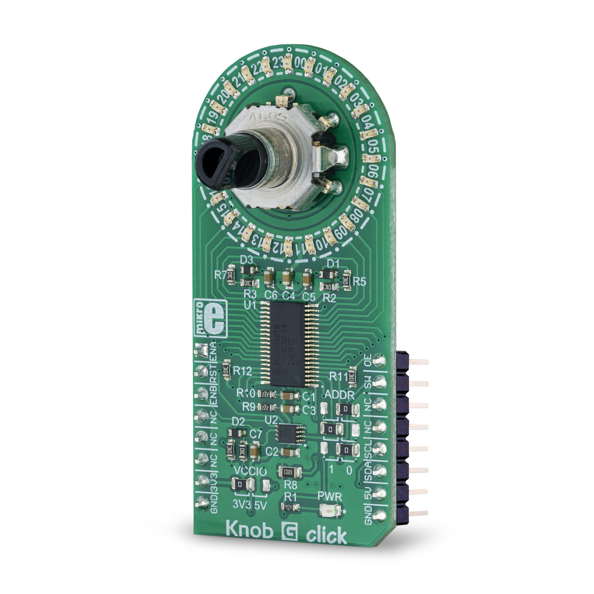
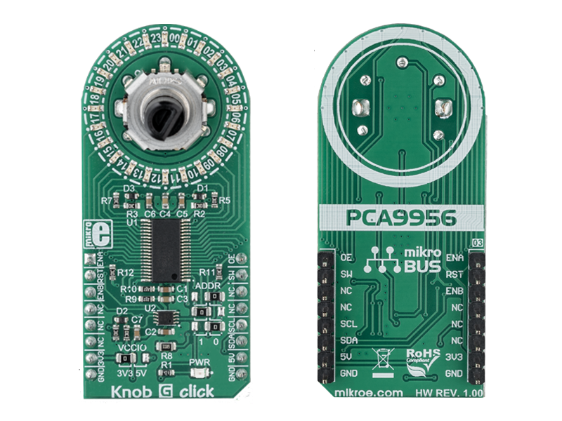
The Knob G click is a Click Board which features a combination of high-quality quadrature rotary encoder, and a LED ring composed of 24 individual green LEDs.

No Abuse Reported

Do you want to subscribe in order to receive notifications regarding "Knob G click" changes.

Do you want to unsubscribe in order to stop receiving notifications regarding "Knob G click" changes.

Do you want to report abuse regarding "Knob G click".

  • mikroSDK Library 2.0.0.0
  • Comments (0)
DOWNLOAD LINK RELATED COMPILER CONTAINS
mikroBasic PRO for ARM
  • lib
  • src
  • exa
  • hlp
  • hex
  • sch
  • pcb
  • doc
mikroBasic PRO for AVR
  • lib
  • src
  • exa
  • hlp
  • hex
  • sch
  • pcb
  • doc
mikroBasic PRO for dsPIC30/33 & PIC24
  • lib
  • src
  • exa
  • hlp
  • hex
  • sch
  • pcb
  • doc
mikroBasic PRO for FT90x
  • lib
  • src
  • exa
  • hlp
  • hex
  • sch
  • pcb
  • doc
mikroBasic PRO for PIC
  • lib
  • src
  • exa
  • hlp
  • hex
  • sch
  • pcb
  • doc
mikroBasic PRO for PIC32
  • lib
  • src
  • exa
  • hlp
  • hex
  • sch
  • pcb
  • doc
mikroC PRO for ARM
  • lib
  • src
  • exa
  • hlp
  • hex
  • sch
  • pcb
  • doc
mikroC PRO for AVR
  • lib
  • src
  • exa
  • hlp
  • hex
  • sch
  • pcb
  • doc
mikroC PRO for dsPIC30/33 & PIC24
  • lib
  • src
  • exa
  • hlp
  • hex
  • sch
  • pcb
  • doc
mikroC PRO for FT90x
  • lib
  • src
  • exa
  • hlp
  • hex
  • sch
  • pcb
  • doc
mikroC PRO for PIC
  • lib
  • src
  • exa
  • hlp
  • hex
  • sch
  • pcb
  • doc
mikroC PRO for PIC32
  • lib
  • src
  • exa
  • hlp
  • hex
  • sch
  • pcb
  • doc
mikroPascal PRO for ARM
  • lib
  • src
  • exa
  • hlp
  • hex
  • sch
  • pcb
  • doc
mikroPascal PRO for AVR
  • lib
  • src
  • exa
  • hlp
  • hex
  • sch
  • pcb
  • doc
mikroPascal PRO for dsPIC30/33 & PIC24
  • lib
  • src
  • exa
  • hlp
  • hex
  • sch
  • pcb
  • doc
mikroPascal PRO for FT90x
  • lib
  • src
  • exa
  • hlp
  • hex
  • sch
  • pcb
  • doc
mikroPascal PRO for PIC
  • lib
  • src
  • exa
  • hlp
  • hex
  • sch
  • pcb
  • doc
mikroPascal PRO for PIC32
  • lib
  • src
  • exa
  • hlp
  • hex
  • sch
  • pcb
  • doc

mikroSDK Library Blog

Knob G click

Knob G click

Native view of the Knob G click board.

View full image
Knob G click

Knob G click

Front and back view of the Knob G click board.

View full image

Library Description

The library initializes and defines the I2C bus driver and drivers that offer a choice for writing data in the register and reads data from the register. The library includes the function for reading the Encoder position and sets a new start position. The user also has the functions for full control LEDs.

Key functions:

  • void knobg_setLedState(uint8_t led, uint8_t state) - Functions for setting the led state
  • void knobg_getEncoderPosition(int32_t *position, uint8_t *dir) - Functions for getting Encoder position
  • void knobg_encoderNewStartPosition(int32_t position) - Functions for set new start encoder position

Examples description

The application is composed of the three sections :

  • System Initialization - Initializes I2C module, sets INT pin, AN pin and CS pin as INPUT and sets RST pin and PWM pin as OUTPUT
  • Application Initialization - Initialization driver init, reset the device, enable led output, set output gain on maximum and sets new start position of the encoder.
  • Application Task - (code snippet) - The Task application has 3 test modes: * The first example is setting BRIGHTNESS on all LEDs. * Other examples put the LED in the position read from the encoder. * The third example sets the LED to be read while the encoder registers the clockwise movement and turn off those LEDs that the encoder reads when moving in a counterclockwise direction. * The example is changed by pressing the SW button
void applicationTask()
{
    knobg_getEncoderPosition(&encoder_newPosition, &direction);
    
    if(knobg_getSWButtonState() == 0)
    {
        SW_State++;
        if(SW_State >= 3) SW_State = 0;
        
        knobg_setBrightness(_KNOBG_BRIGHTNESS_ALL_LED, 0x00);
        Delay_ms( 300 );
    }
    
    /* Logs position */
    if(encoder_newPosition != encoder_oldPosition)
    {
        WordToStr(encoder_newPosition, demoText);
        mikrobus_logWrite(" EnCoder position : ", _LOG_TEXT);
        mikrobus_logWrite(demoText, _LOG_LINE);
    }
    encoder_oldPosition = encoder_newPosition;
    
    switch(SW_State)
    {
        /* Brightness */
        case 0:
        {
            cnt++;
            if(cnt > 127) cnt = 0;
            knobg_setBrightness(_KNOBG_BRIGHTNESS_ALL_LED, cnt);
            Delay_ms( 15 );
            break;
        }
        /* Encoder with one led*/
        case 1:
        {
            if(encoder_newPosition > 24) knobg_encoderNewStartPosition( 1 );
            if(encoder_newPosition < 1) knobg_encoderNewStartPosition( 24 );

            if(direction == 1)
            {
                knobg_setLedState(encoder_newPosition, _KNOBG_LED_ON);
                knobg_setLedState(encoder_newPosition - 1, _KNOBG_LED_OFF);
            }
            else
            {
                knobg_setLedState(encoder_newPosition, _KNOBG_LED_ON);
                knobg_setLedState(encoder_newPosition + 1, _KNOBG_LED_OFF);
            }
            Delay_1ms();
            break;
        }
        /* Encoder with all led */
        case 2:
        {
            if(encoder_newPosition > 24) knobg_encoderNewStartPosition( 1 );
            if(encoder_newPosition < 1) knobg_encoderNewStartPosition( 24 );
            
            if(direction == 1)
            {
                knobg_setLedState(encoder_newPosition, _KNOBG_LED_ON);
            }
            else
            {
                knobg_setLedState(encoder_newPosition + 1, _KNOBG_LED_OFF);
            }
            Delay_1ms();
            break;
        }
    }

}

Other mikroE Libraries used in the example:

  • I2C

Additional notes and information

Depending on the development board you are using, you may need USB UART clickUSB UART 2 click or RS232 click to connect to your PC, for development systems with no UART to USB interface available on the board. The terminal available in all MikroElektronika compilers, or any other terminal application of your choice, can be used to read the message.

ALSO FROM THIS AUTHOR

DIGI POT 3 click

5

DIGI POT 3 click is a versatile and feature-rich digital potentiometer click with 1024 steps and an internal non-volatile memory (EEMEM), which can be used for storing the wiper position, but also for storing various user data.

[Learn More]

Presence Click

0

Presence Click is an infrared sensing Click board™ which can be used for presence sensing, motion detection, and a remote overtemperature protection.

[Learn More]

DIGI POT 2 click

10

DIGI POT 2 click is a mikroBUS add-on board with a single channel digital potentiometer TPL0501 with 256 wiper positions. The IC has 100 kilo Ohms end-to-end resistance, with ±20% tolerance. The board features two pairs of screw terminals for interfacing with the IC DIGI POT 2 click communicates with the target MCU through the mikroBUS SPI.

[Learn More]