TOP Contributors

  1. MIKROE (2784 codes)
  2. Alcides Ramos (405 codes)
  3. Shawon Shahryiar (307 codes)
  4. jm_palomino (133 codes)
  5. Bugz Bensce (97 codes)
  6. S P (73 codes)
  7. dany (71 codes)
  8. MikroBUS.NET Team (35 codes)
  9. NART SCHINACKOW (34 codes)
  10. Armstrong Subero (27 codes)

Most Downloaded

  1. Timer Calculator (141679 times)
  2. FAT32 Library (74727 times)
  3. Network Ethernet Library (59203 times)
  4. USB Device Library (49213 times)
  5. Network WiFi Library (44988 times)
  6. FT800 Library (44517 times)
  7. GSM click (31195 times)
  8. mikroSDK (30081 times)
  9. microSD click (27577 times)
  10. PID Library (27537 times)
Libstock prefers package manager

Package Manager

We strongly encourage users to use Package manager for sharing their code on Libstock website, because it boosts your efficiency and leaves the end user with no room for error. [more info]

< Back
mikroSDK Library

Analog Key click

Rating:

5

Author: MIKROE

Last Updated: 2019-02-21

Package Version: 1.0.0.0

mikroSDK Library: 1.0.0.0

Category: Measurements

Downloaded: 4325 times

Not followed.

License: MIT license  

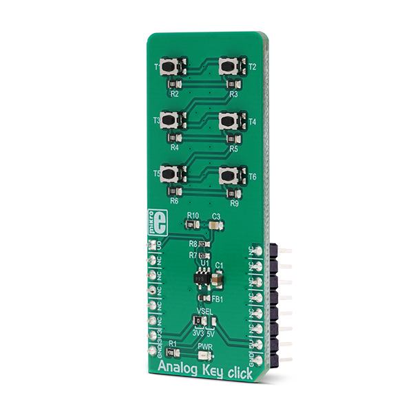
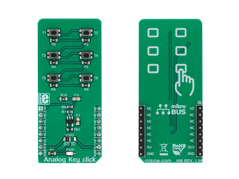
Analog Key Click is an analog keyboard on a Click board. It contains six tactile pushbuttons, used to select one of six different voltage levels.

No Abuse Reported

Do you want to subscribe in order to receive notifications regarding "Analog Key click" changes.

Do you want to unsubscribe in order to stop receiving notifications regarding "Analog Key click" changes.

Do you want to report abuse regarding "Analog Key click".

  • mikroSDK Library 2.0.0.0
  • Comments (0)
DOWNLOAD LINK RELATED COMPILER CONTAINS
mikroBasic PRO for ARM
  • lib
  • src
  • exa
  • hlp
  • hex
  • sch
  • pcb
  • doc
mikroBasic PRO for AVR
  • lib
  • src
  • exa
  • hlp
  • hex
  • sch
  • pcb
  • doc
mikroBasic PRO for dsPIC30/33 & PIC24
  • lib
  • src
  • exa
  • hlp
  • hex
  • sch
  • pcb
  • doc
mikroBasic PRO for FT90x
  • lib
  • src
  • exa
  • hlp
  • hex
  • sch
  • pcb
  • doc
mikroBasic PRO for PIC
  • lib
  • src
  • exa
  • hlp
  • hex
  • sch
  • pcb
  • doc
mikroBasic PRO for PIC32
  • lib
  • src
  • exa
  • hlp
  • hex
  • sch
  • pcb
  • doc
mikroC PRO for ARM
  • lib
  • src
  • exa
  • hlp
  • hex
  • sch
  • pcb
  • doc
mikroC PRO for AVR
  • lib
  • src
  • exa
  • hlp
  • hex
  • sch
  • pcb
  • doc
mikroC PRO for dsPIC30/33 & PIC24
  • lib
  • src
  • exa
  • hlp
  • hex
  • sch
  • pcb
  • doc
mikroC PRO for FT90x
  • lib
  • src
  • exa
  • hlp
  • hex
  • sch
  • pcb
  • doc
mikroC PRO for PIC
  • lib
  • src
  • exa
  • hlp
  • hex
  • sch
  • pcb
  • doc
mikroC PRO for PIC32
  • lib
  • src
  • exa
  • hlp
  • hex
  • sch
  • pcb
  • doc
mikroPascal PRO for ARM
  • lib
  • src
  • exa
  • hlp
  • hex
  • sch
  • pcb
  • doc
mikroPascal PRO for AVR
  • lib
  • src
  • exa
  • hlp
  • hex
  • sch
  • pcb
  • doc
mikroPascal PRO for dsPIC30/33 & PIC24
  • lib
  • src
  • exa
  • hlp
  • hex
  • sch
  • pcb
  • doc
mikroPascal PRO for FT90x
  • lib
  • src
  • exa
  • hlp
  • hex
  • sch
  • pcb
  • doc
mikroPascal PRO for PIC
  • lib
  • src
  • exa
  • hlp
  • hex
  • sch
  • pcb
  • doc
mikroPascal PRO for PIC32
  • lib
  • src
  • exa
  • hlp
  • hex
  • sch
  • pcb
  • doc

mikroSDK Library Blog

Analog Key click

Analog Key click

Native view of the Analog Key click board.

View full image
Analog Key click

Analog Key click

Front and back view of the Analog Key click board.

View full image

Library Description

The library contains a function which, based on the ADC value, detects which button is pressed.

Key functions:

  • uint8_t analogkey_getKey(uint16_t adcValue) - Detects which button is pressed.

Examples description

The application is composed of the three sections :

  • System Initialization - LOG initialization for displaying data on USB UART.
  • Application Initialization - Initializes ADC init.
  • Application Task - (code snippet) - Reads ADC value and detects which button is pressed based on that value.
void applicationTask()
{
    uint16_t ADC_value;
    uint8_t isKey;
    char demoText[ 50 ];
    uint8_t cnt;
    uint16_t sumValue = 0;
    
    for(cnt = 0; cnt < 5; cnt++)
    {
        ADC_value = analogkey_adcRead();
        sumValue += ADC_value;
        Delay_10ms();
    }
    ADC_value = sumValue / 5;
    isKey = analogkey_getKey(ADC_value);
    
    if(isKey != _ANALOGKEY_NO_TOUCH)
    {
        IntToStr(isKey, demoText);
        mikrobus_logWrite("Pressed the button : ", _LOG_TEXT);
        mikrobus_logWrite(demoText, _LOG_LINE);
    }
    Delay_ms( 300 );
}

Other mikroE Libraries used in the example:

  • ADC
  • UART

Additional notes and informations

Depending on the development board you are using, you may need USB UART clickUSB UART 2 clickor RS232 click to connect to your PC, for development systems with no UART to USB interface available on the board. The terminal available in all MikroElektronika compilers, or any other terminal application of your choice, can be used to read the message.

ALSO FROM THIS AUTHOR

UVB click

5

UVB Click is based on GUVB-C31SM ultraviolet sensor from GenUV. UVB Click supports integrated functions of ultraviolet light sensors such that can be easily configured and used in user applications.

[Learn More]

AD SWIO 2 Click

0

AD-SWIO 2 Click is a quad-channel software configurable input/output solution based on AD74413R, for building and process control application. The AD74413R is a quad-channel software configurable input/output solution for building and process control applications. The device provides a fully integrated single chip solution for input and output operation. The AD-SWIO 2 Click contains four 13-bit DACs, one per chanal, and 16-bit Σ-∆ ADC.

[Learn More]

N-PLC Click

0

N-PLC Click is a compact add-on board that uses existing electrical power lines to transmit data signals. This board features the SM2400, an advanced multi-standard Narrow-band Power Line Communication (N-PLC) modem from Semitech. The SM2400 features a dual-core architecture, a DSP core for N-PLC modulations, and a 32-bit core for running protocols for superior communication performance and flexibility for various open standards and customized implementations. It includes firmware options for IEEE 1901.2 compliant PHY and MAC layers, a 6LoWPAN data link layer, and special modes for industrial IoT applications. In addition to the ability to accept signals from another PLC modem or the power line communication AC coupling circuit, this board also has a handful of other features, such as a selectable interface and power supply, firmware update capabilities, LED indicators, and many others.

[Learn More]