TOP Contributors

  1. MIKROE (2784 codes)
  2. Alcides Ramos (405 codes)
  3. Shawon Shahryiar (307 codes)
  4. jm_palomino (133 codes)
  5. Bugz Bensce (97 codes)
  6. S P (73 codes)
  7. dany (71 codes)
  8. MikroBUS.NET Team (35 codes)
  9. NART SCHINACKOW (34 codes)
  10. Armstrong Subero (27 codes)

Most Downloaded

  1. Timer Calculator (141318 times)
  2. FAT32 Library (74154 times)
  3. Network Ethernet Library (58737 times)
  4. USB Device Library (48834 times)
  5. Network WiFi Library (44544 times)
  6. FT800 Library (44120 times)
  7. GSM click (30857 times)
  8. mikroSDK (29699 times)
  9. PID Library (27359 times)
  10. microSD click (27273 times)
Libstock prefers package manager

Package Manager

We strongly encourage users to use Package manager for sharing their code on Libstock website, because it boosts your efficiency and leaves the end user with no room for error. [more info]

< Back
mikroSDK Library

POT click

Rating:

5

Author: MIKROE

Last Updated: 2019-03-08

Package Version: 1.0.0.0

mikroSDK Library: 1.0.0.0

Category: Digital potentiometer

Downloaded: 5009 times

Not followed.

License: MIT license  

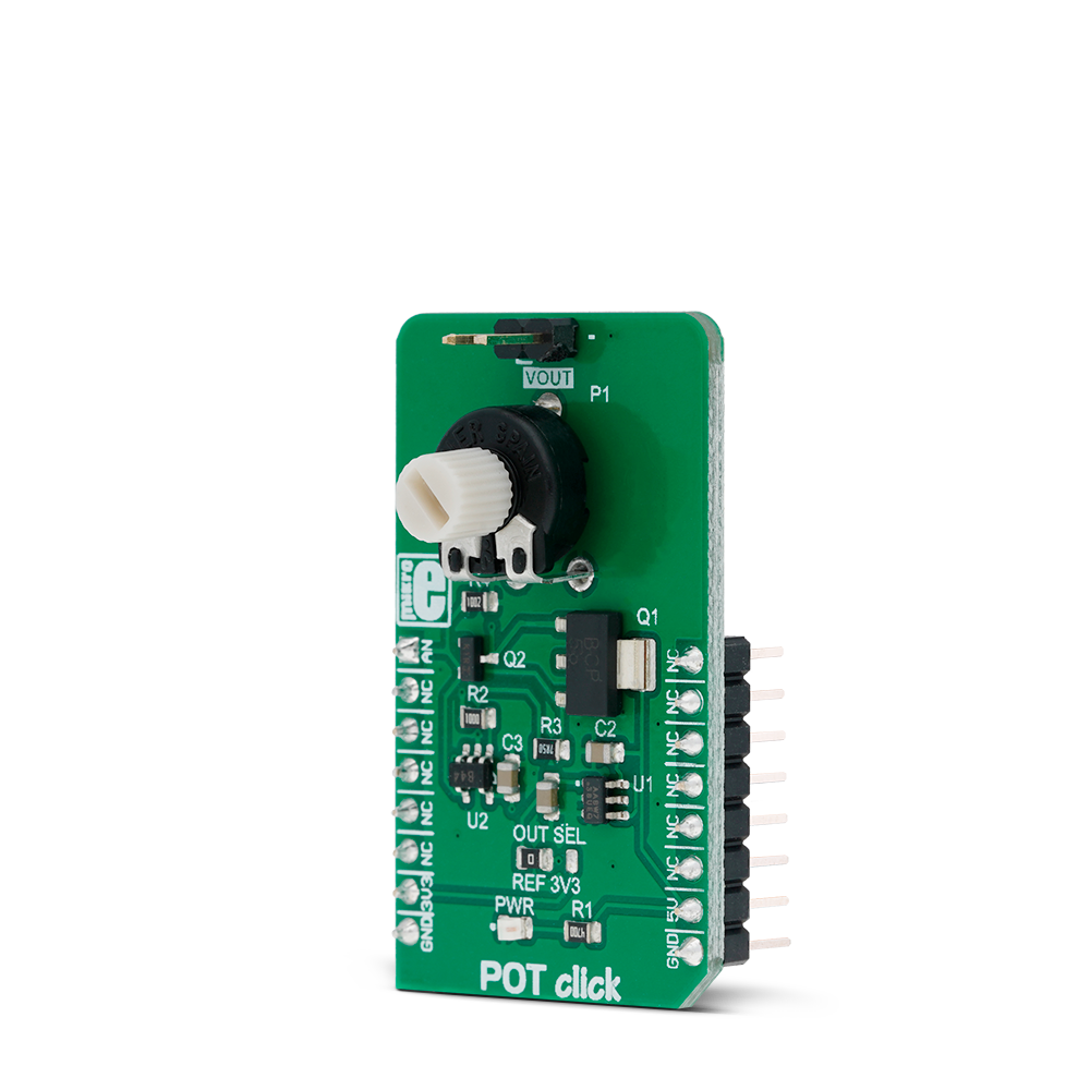
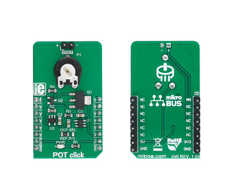
POT Click is a Click board with the accurate selectable reference voltage output. By employing a high-quality 10mm carbon potentiometer, this Click board can provide very accurate voltage output.

No Abuse Reported

Do you want to subscribe in order to receive notifications regarding "POT click" changes.

Do you want to unsubscribe in order to stop receiving notifications regarding "POT click" changes.

Do you want to report abuse regarding "POT click".

  • mikroSDK Library 2.0.0.0
  • Comments (0)
DOWNLOAD LINK RELATED COMPILER CONTAINS
mikroBasic PRO for ARM
  • lib
  • src
  • exa
  • hlp
  • hex
  • sch
  • pcb
  • doc
mikroBasic PRO for AVR
  • lib
  • src
  • exa
  • hlp
  • hex
  • sch
  • pcb
  • doc
mikroBasic PRO for dsPIC30/33 & PIC24
  • lib
  • src
  • exa
  • hlp
  • hex
  • sch
  • pcb
  • doc
mikroBasic PRO for FT90x
  • lib
  • src
  • exa
  • hlp
  • hex
  • sch
  • pcb
  • doc
mikroBasic PRO for PIC
  • lib
  • src
  • exa
  • hlp
  • hex
  • sch
  • pcb
  • doc
mikroBasic PRO for PIC32
  • lib
  • src
  • exa
  • hlp
  • hex
  • sch
  • pcb
  • doc
mikroC PRO for ARM
  • lib
  • src
  • exa
  • hlp
  • hex
  • sch
  • pcb
  • doc
mikroC PRO for AVR
  • lib
  • src
  • exa
  • hlp
  • hex
  • sch
  • pcb
  • doc
mikroC PRO for dsPIC30/33 & PIC24
  • lib
  • src
  • exa
  • hlp
  • hex
  • sch
  • pcb
  • doc
mikroC PRO for FT90x
  • lib
  • src
  • exa
  • hlp
  • hex
  • sch
  • pcb
  • doc
mikroC PRO for PIC
  • lib
  • src
  • exa
  • hlp
  • hex
  • sch
  • pcb
  • doc
mikroC PRO for PIC32
  • lib
  • src
  • exa
  • hlp
  • hex
  • sch
  • pcb
  • doc
mikroPascal PRO for ARM
  • lib
  • src
  • exa
  • hlp
  • hex
  • sch
  • pcb
  • doc
mikroPascal PRO for AVR
  • lib
  • src
  • exa
  • hlp
  • hex
  • sch
  • pcb
  • doc
mikroPascal PRO for dsPIC30/33 & PIC24
  • lib
  • src
  • exa
  • hlp
  • hex
  • sch
  • pcb
  • doc
mikroPascal PRO for FT90x
  • lib
  • src
  • exa
  • hlp
  • hex
  • sch
  • pcb
  • doc
mikroPascal PRO for PIC
  • lib
  • src
  • exa
  • hlp
  • hex
  • sch
  • pcb
  • doc
mikroPascal PRO for PIC32
  • lib
  • src
  • exa
  • hlp
  • hex
  • sch
  • pcb
  • doc

mikroSDK Library Blog

POT click

POT click

Native view of the POT click board.

View full image
POT click

POT click

Front and back view of the POT click board.

View full image

Library Description

The library initializes GPIO interface for the desired mikrobus selection. For more details check documentation.

Key functions:

  • void pot_gpioDriverInit( T_POT_P gpioObj ) - Function initializes GPIO driver for the desired mikrobus.

Examples description

The application is composed of the three sections :

  • System Initialization - Initializes peripherals and pins.
  • Application Initialization - Initializes GPIO interface and ADC.
  • Application Task - (code snippet) - Makes the averaged results by using the desired number of samples of AD conversion. The averaged results will be calculated to millivolts [mV] and sent to the uart terminal. Note : The AD conversion will be performed on the analog (AN) pin on the mikrobus 1.
void applicationTask()
{
    for (nSamples = 0; nSamples < N_SAMPLES; nSamples++)
    {
        adcRead = ADC_Get_Sample( 0 );
        
        if (nSamples == 0)
        {
            adcMax = adcRead;
            adcMin = adcRead;
        }
        if (adcRead > adcMax)
        {
            adcMax = adcRead;
        }
        else if (adcRead < adcMin)
        {
            adcMin = adcRead;
        }
        
        Delay_ms( 1 );
    }

    adcAvrg = adcMax;
    adcAvrg += adcMin;
    adcAvrg /= 2;
    adcAvrg /= ADC_12BIT_RESOL;
    adcAvrg *= ADC_V_REF_MV;
    adcRead = adcAvrg;
    
    WordToStr( adcRead, text );
    mikrobus_logWrite( "** AN : ", _LOG_TEXT );
    mikrobus_logWrite( text, _LOG_TEXT );
    mikrobus_logWrite( " mV **", _LOG_LINE );
    
    Delay_ms( 100 );
}

Other mikroE Libraries used in the example:

  • ADC
  • Conversions
  • UART

Additional notes and informations

Depending on the development board you are using, you may need USB UART clickUSB UART 2 click or RS232 click to connect to your PC, for development systems with no UART to USB interface available on the board. The terminal available in all MikroElektronika compilers, or any other terminal application of your choice, can be used to read the message.

ALSO FROM THIS AUTHOR

DIGI POT 2 click

10

DIGI POT 2 click is a mikroBUS add-on board with a single channel digital potentiometer TPL0501 with 256 wiper positions. The IC has 100 kilo Ohms end-to-end resistance, with ±20% tolerance. The board features two pairs of screw terminals for interfacing with the IC DIGI POT 2 click communicates with the target MCU through the mikroBUS SPI.

[Learn More]

BUCK 7 click

5

Buck 7 click is a high-efficiency buck (step-down) DC-DC converter, which can provide digitally adjusted step-down voltage on its output while delivering up to 3.5A of current.

[Learn More]

MCP2518FD click

5

MCP2518FD Click is a compact add-on board representing a complete CAN solution used as a control node in a CAN network. This board features the MCP2518FD, an external CAN FD controller with an SPI interface, and a high-speed CAN transceiver, the ATA6563, both from Microchip. The ATA6563, a low-level physical layer IC (PHY), provides a physical connection with the CAN bus itself, while the CAN controller MCP2518FD represents an interface between the MCU and the PHY. It features three operating modes with dedicated fail-safe features, remote wake-up via CAN, and ideally passive behavior when powered off on the CAN bus. This Click boardâ„¢ is suitable for developing a wide range of automotive diagnostic applications, even on MCUs that do not natively support CAN interface.

[Learn More]