TOP Contributors

  1. MIKROE (2784 codes)
  2. Alcides Ramos (405 codes)
  3. Shawon Shahryiar (307 codes)
  4. jm_palomino (133 codes)
  5. Bugz Bensce (97 codes)
  6. S P (73 codes)
  7. dany (71 codes)
  8. MikroBUS.NET Team (35 codes)
  9. NART SCHINACKOW (34 codes)
  10. Armstrong Subero (27 codes)

Most Downloaded

  1. Timer Calculator (142095 times)
  2. FAT32 Library (75352 times)
  3. Network Ethernet Library (59524 times)
  4. USB Device Library (49548 times)
  5. Network WiFi Library (45341 times)
  6. FT800 Library (44957 times)
  7. GSM click (31467 times)
  8. mikroSDK (30533 times)
  9. microSD click (27837 times)
  10. PID Library (27631 times)
Libstock prefers package manager

Package Manager

We strongly encourage users to use Package manager for sharing their code on Libstock website, because it boosts your efficiency and leaves the end user with no room for error. [more info]

< Back
mikroSDK Library

DC Motor 11 click

Rating:

5

Author: MIKROE

Last Updated: 2019-07-22

Package Version: 1.0.0.0

mikroSDK Library: 1.0.0.0

Category: Brushed

Downloaded: 4527 times

Not followed.

License: MIT license  

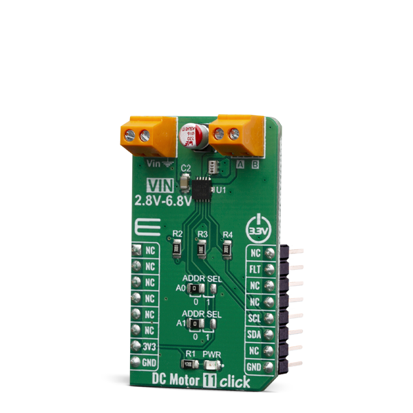
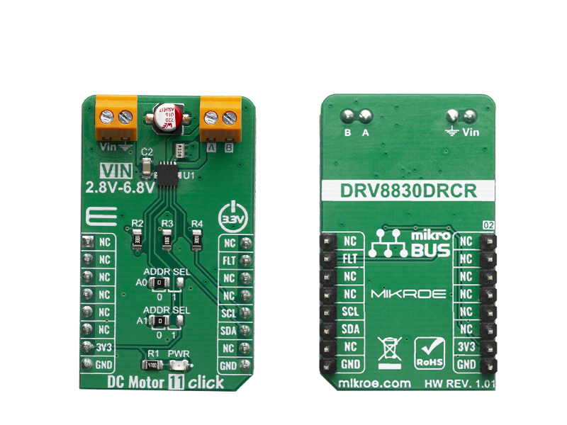
DC Motor 11 Click is a brushed DC motor driver with the current limiting and current sensing. It is based on the DRV8830, an integrated H-Bridge driver IC, optimized for motor driving applications.

No Abuse Reported

Do you want to subscribe in order to receive notifications regarding "DC Motor 11 click" changes.

Do you want to unsubscribe in order to stop receiving notifications regarding "DC Motor 11 click" changes.

Do you want to report abuse regarding "DC Motor 11 click".

  • mikroSDK Library 2.0.0.0
  • Comments (0)
DOWNLOAD LINK RELATED COMPILER CONTAINS
mikroBasic PRO for ARM
  • lib
  • src
  • exa
  • hlp
  • hex
  • sch
  • pcb
  • doc
mikroBasic PRO for AVR
  • lib
  • src
  • exa
  • hlp
  • hex
  • sch
  • pcb
  • doc
mikroBasic PRO for dsPIC30/33 & PIC24
  • lib
  • src
  • exa
  • hlp
  • hex
  • sch
  • pcb
  • doc
mikroBasic PRO for FT90x
  • lib
  • src
  • exa
  • hlp
  • hex
  • sch
  • pcb
  • doc
mikroBasic PRO for PIC
  • lib
  • src
  • exa
  • hlp
  • hex
  • sch
  • pcb
  • doc
mikroBasic PRO for PIC32
  • lib
  • src
  • exa
  • hlp
  • hex
  • sch
  • pcb
  • doc
mikroC PRO for ARM
  • lib
  • src
  • exa
  • hlp
  • hex
  • sch
  • pcb
  • doc
mikroC PRO for AVR
  • lib
  • src
  • exa
  • hlp
  • hex
  • sch
  • pcb
  • doc
mikroBasic PRO for dsPIC30/33 & PIC24
  • lib
  • src
  • exa
  • hlp
  • hex
  • sch
  • pcb
  • doc
mikroC PRO for FT90x
  • lib
  • src
  • exa
  • hlp
  • hex
  • sch
  • pcb
  • doc
mikroC PRO for PIC
  • lib
  • src
  • exa
  • hlp
  • hex
  • sch
  • pcb
  • doc
mikroC PRO for PIC32
  • lib
  • src
  • exa
  • hlp
  • hex
  • sch
  • pcb
  • doc
mikroPascal PRO for ARM
  • lib
  • src
  • exa
  • hlp
  • hex
  • sch
  • pcb
  • doc
mikroPascal PRO for AVR
  • lib
  • src
  • exa
  • hlp
  • hex
  • sch
  • pcb
  • doc
mikroPascal PRO for dsPIC30/33 & PIC24
  • lib
  • src
  • exa
  • hlp
  • hex
  • sch
  • pcb
  • doc
mikroPascal PRO for FT90x
  • lib
  • src
  • exa
  • hlp
  • hex
  • sch
  • pcb
  • doc
mikroPascal PRO for PIC
  • lib
  • src
  • exa
  • hlp
  • hex
  • sch
  • pcb
  • doc
mikroPascal PRO for PIC32
  • lib
  • src
  • exa
  • hlp
  • hex
  • sch
  • pcb
  • doc

mikroSDK Library Blog

DC Motor 11 click

DC Motor 11 click

Native view of the DC Motor 11 click board.

View full image
DC Motor 11 click

DC Motor 11 click

Front and back view of the DC Motor 11 click board.

View full image

Library Description

The library contains all the necessary functions for full DC motor control.

Key functions:

  • void dcmotor11_control(uint8_t dir, uint8_t speed) - Motor Control.
  • void dcmotor11_stop() - Motor Stop.
  • uint8_t dcmotor11_getFault() - Get Fault.

Examples description

The application is composed of three sections :

  • System Initialization - Initialzes I2C module and sets INT pin as INPUT
  • Application Initialization - Initialization driver init and sets first motor settings.
  • Application Task - Waits for valid user input and executes functions based on set of valid commands.
  • Commands : '+' - Voltage (Speed) up '-' - Voltage (Speed) down 's' - Motor State - Stop/Start 'd' - Direction - Forword/Backword
void applicationTask()
{
    uint8_t dataReady_;
    char receivedData_;

    dataReady_ = UART_Rdy_Ptr( );

    if (dataReady_ != 0)
    {
        receivedData_ = UART_Rd_Ptr( );

        switch (receivedData_)
        {
            case '+' :
            {
                /* Speed increase */
                motorSpeed += 4;
                if(motorSpeed >= _DCMOTOR11_VSET_4820mV)
                {
                    mikrobus_logWrite("---- MAX SPEED ----", _LOG_LINE);
                    motorSpeed = _DCMOTOR11_VSET_4820mV;
                    dcmotor11_control(motorDir, motorSpeed);
                }
                else
                {
                    mikrobus_logWrite("---- Speed increase ----", _LOG_TEXT);
                    
                    mikrobus_logWrite(" MOTOR SPEED: ", _LOG_TEXT);
                    IntToStr(motorSpeed, demoText);
                    mikrobus_logWrite(demoText, _LOG_LINE);
                    
                    dcmotor11_control(motorDir, motorSpeed);
                }
                break;
            }
            case '-' :
            {
                /* Speed decrease */
                motorSpeed -= 4;
                if( motorSpeed < _DCMOTOR11_VSET_480mV )
                {
                    mikrobus_logWrite("---- MIN SPEED ----", _LOG_LINE);
                    motorSpeed = _DCMOTOR11_VSET_480mV;
                }
                else
                {
                    mikrobus_logWrite("---- Speed decrease ----", _LOG_TEXT);
                    
                    mikrobus_logWrite(" MOTOR SPEED: ", _LOG_TEXT);
                    IntToStr(motorSpeed, demoText);
                    mikrobus_logWrite(demoText, _LOG_LINE);
                    
                    dcmotor11_control(motorDir, motorSpeed);
                }
                break;
            }
            case 's' :
            {
                /* Stop / Start */
                if(fMotorState == 1)
                {
                     mikrobus_logWrite("---- Stop Motor!!! ----", _LOG_LINE);
                     fMotorState = 0;
                     dcmotor11_stop();
                }
                else
                {
                    mikrobus_logWrite("---- Start Motor ----", _LOG_LINE);
                    fMotorState = 1;
                    motorSpeed = _DCMOTOR11_VSET_480mV;
                    dcmotor11_control(motorDir, motorSpeed);
                }
                break;
            }
            case 'd' :
            {
                /* Direction - Forward / Backword */
                if(motorDir == 2)
                {
                     mikrobus_logWrite("---- Direction - [FORWARD] ----", _LOG_LINE);
                     motorDir = 1;
                     dcmotor11_control(motorDir, motorSpeed);
                }
                else
                {
                    mikrobus_logWrite("---- Direction - [BACKWARD] ----", _LOG_LINE);
                    motorDir = 2;
                    dcmotor11_control(motorDir, motorSpeed);
                }
                break;
            }
        }
    }
}


The full application code, and ready to use projects can be found on our LibStock page.

Other mikroE Libraries used in the example:

  • I2C
  • UART
  • Conversions

Additional notes and informations

Depending on the development board you are using, you may need USB UART clickUSB UART 2 click or RS232 click to connect to your PC, for development systems with no UART to USB interface available on the board. The terminal available in all MikroElektronika compilers, or any other terminal application of your choice, can be used to read the message.

ALSO FROM THIS AUTHOR

MCP2517FD click

6

MCP2517FD Click is a compact add-on board representing a complete CAN solution used as a control node in a CAN network. This board features the MCP2517FD and ATA6563, an external CAN FD controller with an SPI interface, and a high-speed CAN transceiver from Microchip. The ATA6563, a low-level physical layer IC (PHY), provides a physical connection with the CAN bus itself, while the CAN controller MCP2517FD represents an interface between the MCU and the PHY. It features three operating modes with dedicated fail-safe features, remote wake-up via CAN, and ideally passive behavior when powered off on the CAN bus. This Click board™ is suitable for developing a wide range of automotive diagnostic applications, even on MCUs that don’t support CAN interface.

[Learn More]

eINK 2.90 inch display

5

This bundle comes with the eINK click adapter and e-Paper display 2.9”. Which provides you an easy start of any project where the e-paper display is needed.

[Learn More]

CXPI click

5

CXPI Click is a compact add-on board that contains a transceiver that supports the next-generation automotive communication protocol. This board features the BD41000AFJ-C, a transceiver for the CXPI (Clock Extension Peripheral Interface) communication from Rohm Semiconductor.

[Learn More]