TOP Contributors

  1. MIKROE (2784 codes)
  2. Alcides Ramos (388 codes)
  3. Shawon Shahryiar (307 codes)
  4. jm_palomino (120 codes)
  5. Bugz Bensce (97 codes)
  6. S P (73 codes)
  7. dany (71 codes)
  8. MikroBUS.NET Team (35 codes)
  9. NART SCHINACKOW (34 codes)
  10. Armstrong Subero (27 codes)

Most Downloaded

  1. Timer Calculator (140362 times)
  2. FAT32 Library (72764 times)
  3. Network Ethernet Library (57875 times)
  4. USB Device Library (48023 times)
  5. Network WiFi Library (43608 times)
  6. FT800 Library (43041 times)
  7. GSM click (30173 times)
  8. mikroSDK (28850 times)
  9. PID Library (27078 times)
  10. microSD click (26605 times)
Libstock prefers package manager

Package Manager

We strongly encourage users to use Package manager for sharing their code on Libstock website, because it boosts your efficiency and leaves the end user with no room for error. [more info]

< Back
mikroSDK Library

Step Up click

Rating:

5

Author: MIKROE

Last Updated: 2019-08-15

Package Version: 1.0.0.0

mikroSDK Library: 1.0.0.0

Category: Boost

Downloaded: 2875 times

Not followed.

License: MIT license  

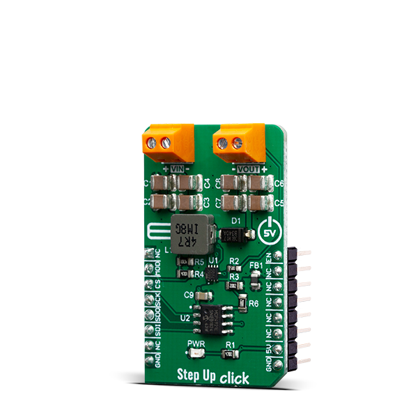
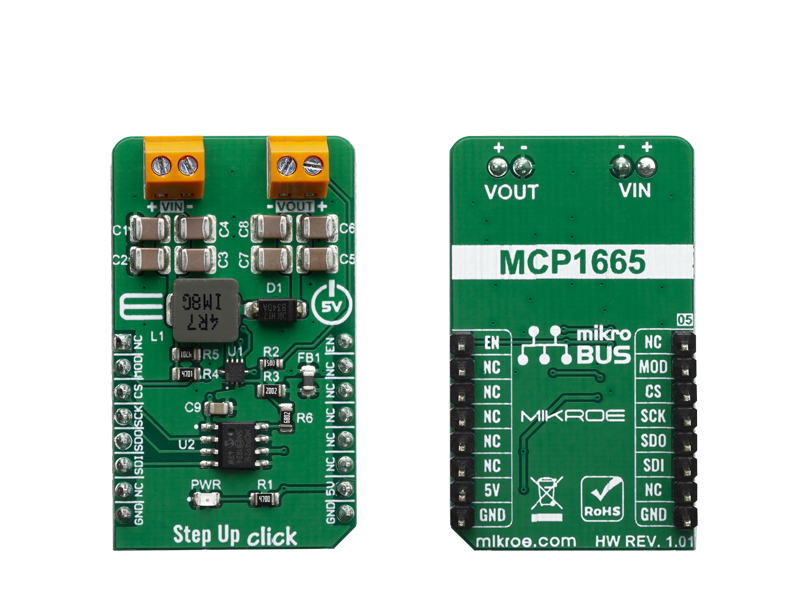
Step Up Click is a fixed frequency DC-DC step-up (boost) regulator, which can be obtained from any low voltage input - such as NiCd, NiMH or one cell Li-Po/Li-Ion batteries.

No Abuse Reported

Do you want to subscribe in order to receive notifications regarding "Step Up click" changes.

Do you want to unsubscribe in order to stop receiving notifications regarding "Step Up click" changes.

Do you want to report abuse regarding "Step Up click".

  • mikroSDK Library 2.0.0.0
  • Comments (0)
DOWNLOAD LINK RELATED COMPILER CONTAINS
mikroBasic PRO for ARM
  • lib
  • src
  • exa
  • hlp
  • hex
  • sch
  • pcb
  • doc
mikroBasic PRO for AVR
  • lib
  • src
  • exa
  • hlp
  • hex
  • sch
  • pcb
  • doc
mikroBasic PRO for dsPIC30/33 & PIC24
  • lib
  • src
  • exa
  • hlp
  • hex
  • sch
  • pcb
  • doc
mikroBasic PRO for FT90x
  • lib
  • src
  • exa
  • hlp
  • hex
  • sch
  • pcb
  • doc
mikroBasic PRO for PIC
  • lib
  • src
  • exa
  • hlp
  • hex
  • sch
  • pcb
  • doc
mikroBasic PRO for PIC32
  • lib
  • src
  • exa
  • hlp
  • hex
  • sch
  • pcb
  • doc
mikroC PRO for ARM
  • lib
  • src
  • exa
  • hlp
  • hex
  • sch
  • pcb
  • doc
mikroC PRO for AVR
  • lib
  • src
  • exa
  • hlp
  • hex
  • sch
  • pcb
  • doc
mikroC PRO for dsPIC30/33 & PIC24
  • lib
  • src
  • exa
  • hlp
  • hex
  • sch
  • pcb
  • doc
mikroC PRO for FT90x
  • lib
  • src
  • exa
  • hlp
  • hex
  • sch
  • pcb
  • doc
mikroC PRO for PIC
  • lib
  • src
  • exa
  • hlp
  • hex
  • sch
  • pcb
  • doc
mikroC PRO for PIC32
  • lib
  • src
  • exa
  • hlp
  • hex
  • sch
  • pcb
  • doc
mikroPascal PRO for ARM
  • lib
  • src
  • exa
  • hlp
  • hex
  • sch
  • pcb
  • doc
mikroPascal PRO for AVR
  • lib
  • src
  • exa
  • hlp
  • hex
  • sch
  • pcb
  • doc
mikroPascal PRO for dsPIC30/33 & PIC24
  • lib
  • src
  • exa
  • hlp
  • hex
  • sch
  • pcb
  • doc
mikroPascal PRO for FT90x
  • lib
  • src
  • exa
  • hlp
  • hex
  • sch
  • pcb
  • doc
mikroPascal PRO for PIC
  • lib
  • src
  • exa
  • hlp
  • hex
  • sch
  • pcb
  • doc
mikroPascal PRO for PIC32
  • lib
  • src
  • exa
  • hlp
  • hex
  • sch
  • pcb
  • doc

mikroSDK Library Blog

Step up click

Step up click

Native view of the Step up click board.

View full image
Step up click

Step up click

Front and back view of the Step up click board.

View full image

Library Description

Library contains functions for setting states of RST and PWM pins Library contains function for setting configuratoin word Library contains function for setting output value Library contains function for calculating output value expressed in percent Library contains function for device initialization.

Key functions:

  • uint8_t stepup_setConfig( uint16_t config ) - sets first 4 bits in command word.
  • uint8_t stepup_setOut( uint16_t out_value ) - sets output value.
  • void stepup_init(void) - initializes the device.

Examples description

The application is composed of three sections :

  • System Initialization - Initializes SPI, LOG, RST, CS and PWM pins
  • Application Initialization - Initializes SPI driver, sets config word, initializes the device, sets and log output value
  • Application Task - Checks for user input in UART terminal, if user enters + or - output value is increased or decreased respectively
void applicationTask( )
{
    if (UART_Data_Ready( ) == 1)
    {
        uart_char = UART_Read( );
        switch ( uart_char )
        {
            case '-' :
            {
                if (out_value < 4095)
                {
                    out_value++;
                }
                stepup_setOut( out_value );
                stepup_logPercent( out_value );
                break;
            }
            case '+' :
            {
                if (out_value > 0)
                {
                    out_value--;
                }
                stepup_setOut( out_value );
                stepup_logPercent( out_value );
                break;
            }
            default :
            {
                mikrobus_logWrite( "error : invalid command", _LOG_LINE );
                break;
            }
        }
    }
}


Additional Functions :

  • stepup_logPercent() - calls 'stepup_getPercent()' function to get output value in expressed as percentage and logs that value

Other mikroE Libraries used in the example:

  • SPI
  • UART
  • Conversions

Additional notes and informations

Depending on the development board you are using, you may need USB UART clickUSB UART 2 click or RS232 click to connect to your PC, for development systems with no UART to USB interface available on the board. The terminal available in all MikroElektronika compilers, or any other terminal application of your choice, can be used to read the message.

ALSO FROM THIS AUTHOR

LED Driver 13 Click

0

LED Driver 13 Click is a compact add-on board that simplifies the control of multiple LEDs. This board features the A80604-1, a 4-channel LED driver designed at a switching frequency of 400kHz that provides 150mA per channel from Allegro Microsystems. It is powered by an external power supply in the range of 6V to 18V, providing an output voltage of approximately 26V, which is used to power LEDs connected to LED channels. On the logical side, this board uses both 3V3 and 5V with mikroBUS™ power rails and communicates with the MCU via GPIO pins. In addition, the user is given the option of analog or digital LED dimming selection, using a PWM pin from the mikroBUS™ socket or via an onboard potentiometer/external PWM signal.

[Learn More]

ADC 13 Click

0

ADC 13 Click is a compact add-on board that contains a high-performance data converter. This board features the ADS1262, a 32-bit, high precision, 38-kSPS, analog-to-digital converter with programmable gain amplifier and voltage reference from Texas Instruments.

[Learn More]

One Shot click

5

One Shot click is a is a monostable multivibrator (also known as a “one-shot” pulse generator) with a programmable pulse width of 1μs to 33.6 seconds.

[Learn More]