TOP Contributors

  1. MIKROE (2762 codes)
  2. Alcides Ramos (374 codes)
  3. Shawon Shahryiar (307 codes)
  4. jm_palomino (118 codes)
  5. Bugz Bensce (90 codes)
  6. S P (73 codes)
  7. dany (71 codes)
  8. MikroBUS.NET Team (35 codes)
  9. NART SCHINACKOW (34 codes)
  10. Armstrong Subero (27 codes)

Most Downloaded

  1. Timer Calculator (139248 times)
  2. FAT32 Library (71743 times)
  3. Network Ethernet Library (57115 times)
  4. USB Device Library (47428 times)
  5. Network WiFi Library (43082 times)
  6. FT800 Library (42403 times)
  7. GSM click (29835 times)
  8. mikroSDK (28073 times)
  9. PID Library (26885 times)
  10. microSD click (26198 times)
Libstock prefers package manager

Package Manager

We strongly encourage users to use Package manager for sharing their code on Libstock website, because it boosts your efficiency and leaves the end user with no room for error. [more info]

< Back
mikroSDK Library

Power/Reset click

Rating:

5

Author: MIKROE

Last Updated: 2019-10-04

Package Version: 1.0.0.0

mikroSDK Library: 1.0.0.0

Category: Capacitive

Downloaded: 3205 times

Not followed.

License: MIT license  

Power/Reset Click is equipped with two capacitive touch pads on a single click boardâ„¢. It can be activated by touch, and unlike the mechanical button, the capacitive touch button lasts much longer, it is not prone to damage and wear over time and it is very reliable.

No Abuse Reported

Do you want to subscribe in order to receive notifications regarding "Power/Reset click" changes.

Do you want to unsubscribe in order to stop receiving notifications regarding "Power/Reset click" changes.

Do you want to report abuse regarding "Power/Reset click".
  • mikroSDK Library 2.0.0.0
  • Comments (0)
DOWNLOAD LINK RELATED COMPILER CONTAINS
mikroBasic PRO for ARM
  • lib
  • src
  • exa
  • hlp
  • hex
  • sch
  • pcb
  • doc
mikroBasic PRO for AVR
  • lib
  • src
  • exa
  • hlp
  • hex
  • sch
  • pcb
  • doc
mikroBasic PRO for dsPIC30/33 & PIC24
  • lib
  • src
  • exa
  • hlp
  • hex
  • sch
  • pcb
  • doc
mikroBasic PRO for FT90x
  • lib
  • src
  • exa
  • hlp
  • hex
  • sch
  • pcb
  • doc
mikroBasic PRO for PIC
  • lib
  • src
  • exa
  • hlp
  • hex
  • sch
  • pcb
  • doc
mikroBasic PRO for PIC32
  • lib
  • src
  • exa
  • hlp
  • hex
  • sch
  • pcb
  • doc
mikroC PRO for ARM
  • lib
  • src
  • exa
  • hlp
  • hex
  • sch
  • pcb
  • doc
mikroC PRO for AVR
  • lib
  • src
  • exa
  • hlp
  • hex
  • sch
  • pcb
  • doc
mikroC PRO for dsPIC30/33 & PIC24
  • lib
  • src
  • exa
  • hlp
  • hex
  • sch
  • pcb
  • doc
mikroC PRO for FT90x
  • lib
  • src
  • exa
  • hlp
  • hex
  • sch
  • pcb
  • doc
mikroC PRO for PIC
  • lib
  • src
  • exa
  • hlp
  • hex
  • sch
  • pcb
  • doc
mikroC PRO for PIC32
  • lib
  • src
  • exa
  • hlp
  • hex
  • sch
  • pcb
  • doc
mikroPascal PRO for ARM
  • lib
  • src
  • exa
  • hlp
  • hex
  • sch
  • pcb
  • doc
mikroPascal PRO for AVR
  • lib
  • src
  • exa
  • hlp
  • hex
  • sch
  • pcb
  • doc
mikroPascal PRO for dsPIC30/33 & PIC24
  • lib
  • src
  • exa
  • hlp
  • hex
  • sch
  • pcb
  • doc
mikroPascal PRO for FT90x
  • lib
  • src
  • exa
  • hlp
  • hex
  • sch
  • pcb
  • doc
mikroPascal PRO for PIC
  • lib
  • src
  • exa
  • hlp
  • hex
  • sch
  • pcb
  • doc
mikroPascal PRO for PIC32
  • lib
  • src
  • exa
  • hlp
  • hex
  • sch
  • pcb
  • doc

mikroSDK Library Blog

Power/Reset click

Power/Reset click

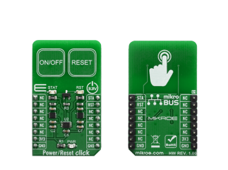
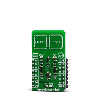
Native view of the Power/Reset click board.

View full image
Power/Reset click

Power/Reset click

Front and back view of the Power/Reset click board.

View full image

Library Description

This library allows user to check which button is pressed or activated. Also initializes GPIO driver. For more details check documentation.

Key functions:

  • void touchbutt_gpioDriverInit(T_TOUCHBUTT_P gpioObj) - This function initializes GPIO driver.
  • T_TOUCHBUTT_STATE touchbutt_getPWR( void ) - This function returns a state of the PWR pin (ON/OFF button).
  • T_TOUCHBUTT_STATE touchbutt_getRST( void ) - This function returns a state of the RST pin (RESET button).

Examples description

The application is composed of three sections :

  • System Initialization - Initializes peripherals and pins.
  • Application Initialization - Initializes GPIO driver and performs a timer interrupt configuration.
  • Application Task - (code snippet) - Checks the states of the PWR and RST pins and performs a control of the timer counter depending on the pressed button (pins state). User can start and stop a timer counter, in the resolution of 100ms, by pressing the ON/OFF button. Also can reset a timer counter to 0 by pressing the RESET button. When timer counter was reached the target time (in seconds), a message will be sent to the uart terminal and the sound will be generated. Timer counter state will be showed to the uart terminal.
void applicationTask()
{
    pwr_state = touchbutt_getPWR();
    rst_state = touchbutt_getRST();
    
    if ((pwr_state == _TOUCHBUTT_ACTIVE) && (time_cnt_prev != time_cnt) && (rst_state == _TOUCHBUTT_INACTIVE))
    {
        time_val_dec = time_cnt / 10;
        time_val_real = time_cnt % 10;
        
        LongWordToStr( time_val_dec, text );
        Ltrim( text );
        mikrobus_logWrite( text, _LOG_TEXT );
        mikrobus_logWrite( ".", _LOG_TEXT );
        ByteToStr( time_val_real, text );
        Ltrim( text );
        mikrobus_logWrite( text, _LOG_LINE );
        
        if ((time_val_dec >= target_time) && (alarm_flag == _TOUCHBUTT_ACTIVE))
        {
            mikrobus_logWrite( "** Target time is reached! **", _LOG_LINE );
            alarm_flag = _TOUCHBUTT_INACTIVE;
            
            Sound_Play( 1000, 50 );
            Delay_ms( 40 );
            Sound_Play( 1000, 50 );
            Delay_ms( 40 );
        }
    }
    
    if (rst_state == _TOUCHBUTT_ACTIVE)
    {
        time_cnt = 0;
        alarm_flag = _TOUCHBUTT_ACTIVE;
    }
    else
    {
        time_cnt_prev = time_cnt;
    }
}


The full application code, and ready to use projects can be found on our LibStock page.

Other mikroE Libraries used in the example:

  • Conversions
  • C_String
  • Sound
  • UART

Additional notes and informations

Depending on the development board you are using, you may need USB UART clickUSB UART 2 click or RS232 click to connect to your PC, for development systems with no UART to USB interface available on the board. The terminal available in all MikroElektronika compilers, or any other terminal application of your choice, can be used to read the message.

ALSO FROM THIS AUTHOR

10x10 RGB 2 Click

0

10x10 RGB 2 Click is a compact add-on board designed for creating vibrant LED displays and lighting solutions. This board features the IN-PC20TBT5R5G5B, an RGB LED with an advanced IC for seamless operation from Inolux. The board features a 10x10 matrix of smart RGB LEDs capable of dual-wire transmission and a sophisticated control circuit for dynamic color rendering. It incorporates CMOS technology for low power consumption and supports 256 grayscale levels for precise PWM dimming, along with 32 levels of brightness control.

[Learn More]

CAN Bus Click

0

CAN Bus Click is a compact add-on board that provides a link between the CAN protocol controller and the physical wires of the bus lines in a control area network (CAN). This board features the MAX13054, an industry-standard, high-speed CAN transceiver with extended ±80V fault protection from Maxim Integrated.

[Learn More]

DC MOTOR 7 Click

0

DC MOTOR 7 Click is a dual brushed DC motor driving Click board™, featuring the advanced PWM chopper-type integrated DC motor driver, labeled as TB67H400AFTG.

[Learn More]