TOP Contributors

  1. MIKROE (2784 codes)
  2. Alcides Ramos (405 codes)
  3. Shawon Shahryiar (307 codes)
  4. jm_palomino (133 codes)
  5. Bugz Bensce (97 codes)
  6. S P (73 codes)
  7. dany (71 codes)
  8. MikroBUS.NET Team (35 codes)
  9. NART SCHINACKOW (34 codes)
  10. Armstrong Subero (27 codes)

Most Downloaded

  1. Timer Calculator (141265 times)
  2. FAT32 Library (74088 times)
  3. Network Ethernet Library (58715 times)
  4. USB Device Library (48823 times)
  5. Network WiFi Library (44525 times)
  6. FT800 Library (44072 times)
  7. GSM click (30803 times)
  8. mikroSDK (29654 times)
  9. PID Library (27355 times)
  10. microSD click (27251 times)
Libstock prefers package manager

Package Manager

We strongly encourage users to use Package manager for sharing their code on Libstock website, because it boosts your efficiency and leaves the end user with no room for error. [more info]

< Back
mikroSDK Library

Buck 14 click

Rating:

5

Author: MIKROE

Last Updated: 2019-11-18

Package Version: 1.0.0.0

mikroSDK Library: 1.0.0.0

Category: Buck

Downloaded: 3351 times

Not followed.

License: MIT license  

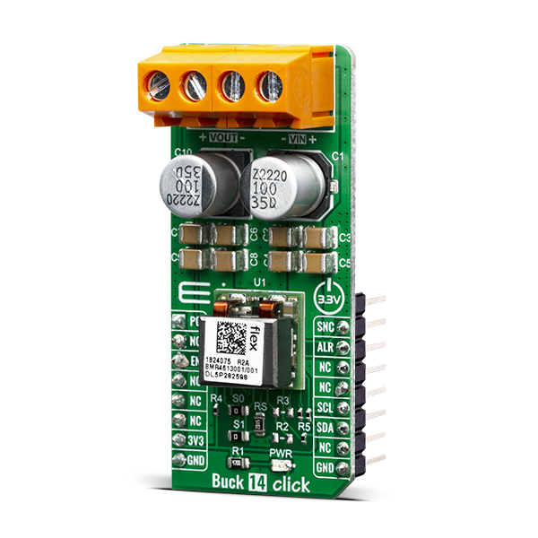
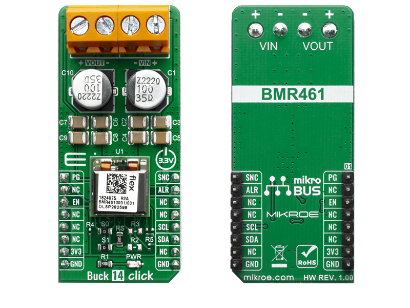
The Buck 14 click is a Click board based around the BMR4613001/001, a PoL regulator from Flex. It's igh-efficiency step-down converter which provides a highly regulated output voltage derived from the connected power source, rated from 4.5 to 14V.

No Abuse Reported

Do you want to subscribe in order to receive notifications regarding "Buck 14 click" changes.

Do you want to unsubscribe in order to stop receiving notifications regarding "Buck 14 click" changes.

Do you want to report abuse regarding "Buck 14 click".

  • mikroSDK Library 2.0.0.0
  • Comments (0)
DOWNLOAD LINK RELATED COMPILER CONTAINS
mikroBasic PRO for ARM
  • lib
  • src
  • exa
  • hlp
  • hex
  • sch
  • pcb
  • doc
mikroBasic PRO for AVR
  • lib
  • src
  • exa
  • hlp
  • hex
  • sch
  • pcb
  • doc
mikroBasic PRO for dsPIC30/33 & PIC24
  • lib
  • src
  • exa
  • hlp
  • hex
  • sch
  • pcb
  • doc
mikroBasic PRO for FT90x
  • lib
  • src
  • exa
  • hlp
  • hex
  • sch
  • pcb
  • doc
mikroBasic PRO for PIC
  • lib
  • src
  • exa
  • hlp
  • hex
  • sch
  • pcb
  • doc
mikroBasic PRO for PIC32
  • lib
  • src
  • exa
  • hlp
  • hex
  • sch
  • pcb
  • doc
mikroC PRO for ARM
  • lib
  • src
  • exa
  • hlp
  • hex
  • sch
  • pcb
  • doc
mikroC PRO for AVR
  • lib
  • src
  • exa
  • hlp
  • hex
  • sch
  • pcb
  • doc
mikroC PRO for dsPIC30/33 & PIC24
  • lib
  • src
  • exa
  • hlp
  • hex
  • sch
  • pcb
  • doc
mikroC PRO for FT90x
  • lib
  • src
  • exa
  • hlp
  • hex
  • sch
  • pcb
  • doc
mikroC PRO for PIC
  • lib
  • src
  • exa
  • hlp
  • hex
  • sch
  • pcb
  • doc
mikroC PRO for PIC32
  • lib
  • src
  • exa
  • hlp
  • hex
  • sch
  • pcb
  • doc
mikroPascal PRO for ARM
  • lib
  • src
  • exa
  • hlp
  • hex
  • sch
  • pcb
  • doc
mikroPascal PRO for AVR
  • lib
  • src
  • exa
  • hlp
  • hex
  • sch
  • pcb
  • doc
mikroPascal PRO for dsPIC30/33 & PIC24
  • lib
  • src
  • exa
  • hlp
  • hex
  • sch
  • pcb
  • doc
mikroPascal PRO for FT90x
  • lib
  • src
  • exa
  • hlp
  • hex
  • sch
  • pcb
  • doc
mikroPascal PRO for PIC
  • lib
  • src
  • exa
  • hlp
  • hex
  • sch
  • pcb
  • doc
mikroPascal PRO for PIC32
  • lib
  • src
  • exa
  • hlp
  • hex
  • sch
  • pcb
  • doc

mikroSDK Library Blog

Buck 14 click

Buck 14 click

Native view of the Buck 14 click board.

View full image
Buck 14 click

Buck 14 click

Front and back view of the Buck 14 click board.

View full image

Library Description

Library provides control over device pins, you can read state of some pins. You have ability to send and receive data from device, and control output V.

Key functions:

  • void buck14_read_data (uint8_t cmd, uint8_t *data_buf, uint8_t n_buf_size ) - Reads data from specific registar to buffer
  • void buck14_write_data (uint8_t cmd, uint8_t *data_buf, uint8_t n_buf_size ) - Writes data to specific registar to buffer
  • uint8_t buc14_write_vout( float vout ) - Sets output V
  • uint16_t buc14_read_vout( void ) - Returns output V in mV

Examples description

The application is composed of three sections :

  • System Initialization - Initialization of SPI module and setting pins to output
  • Application Initialization - Configure device, checks id, writes default command VOUT, checks if power is OK
  • Application Task - Sends 4 different commands for VOUT in span of 8sec
void application_task ( )
{
    vout_value = 1.2;
    status_data = buc14_write_vout( vout_value );
    error_handler( status_data );

    if ( status_data == BUCK14_SUCCESSFUL )
    {
        read_vout_data(  );
    }

    Delay_ms( 8000 );

    vout_value = 3.7;
    status_data = buc14_write_vout( vout_value );
    error_handler( status_data );

    if ( status_data == BUCK14_SUCCESSFUL )
    {
        read_vout_data(  );
    }

    Delay_ms( 8000 );
    
    vout_value = 2.5;
    status_data = buc14_write_vout( vout_value );
    error_handler( status_data );

    if ( status_data == BUCK14_SUCCESSFUL )
    {
        read_vout_data(  );
    }
    
    Delay_ms( 8000 );

    vout_value = 4.5;
    status_data = buc14_write_vout( vout_value );
    error_handler( status_data );

    if ( status_data == BUCK14_SUCCESSFUL )
    {
        read_vout_data(  );
    }
    
    Delay_ms( 4000 );
    mikrobus_logWrite( "```````````````", _LOG_LINE );
    Delay_ms( 4000 );
}

Additional Functions :

  • void error_handler ( uint8_t stat_data ) - Check if there was error in stat_data and returns message
  • void read_vout_data ( void ) - Reads current VOUT in mV

Note :

  • When you send data you should send LSB first
  • Device input V should be beetween 4.5 - 14 V
  • Device output V could be from 0.5 - 5 V deepending from limits you set currently it is set to 1V

Other mikroE Libraries used in the example:

  • Conversions
  • I2C
  • UART

Additional notes and informations

Depending on the development board you are using, you may need USB UART clickUSB UART 2 click or RS232 click to connect to your PC, for development systems with no UART to USB interface available on the board. The terminal available in all MikroElektronika compilers, or any other terminal application of your choice, can be used to read the message.

ALSO FROM THIS AUTHOR

USB SPI click - Example

0

This is a sample program which demonstrates the use of USB SPI click This device accepts commands from SPI Terminal and sends appropriate bytes via SPI interface. It is very desirable tool for designing SPI slave devices such as sensors...

[Learn More]

IrThermo 5V Click

0

IrThermo Click 5V is a contactless temperature measurement device that relies on the accurate thermopile sensor chip, which encompasses both the thermopile sensor element and the ASSP. The ASSP - signal conditioning circuitry features 17bit ADC and powerful DSP which allow high degree of accuracy and wide temperature measurement range. The IrThermo Click is equipped with both the 10bit PWM interface and the SMBus/I2C interface.

[Learn More]

Color 17 Click

0

Color 17 Click is a compact add-on board representing an accurate color-sensing solution. This board features the OPT4048, a high-speed precision tristimulus XYZ color sensor from Texas Instruments. The sensor has four sensing channels and uses precision optical filters to mimic the normal vision of the human eye. The OPT4048 also has 12 configurable conversion times that range from 600μs up to 800ms, with measurements that can be read synchronously or asynchronously. It is not excessively sensitive to micro-shadows and the small particles on the optical surface.

[Learn More]