TOP Contributors

  1. MIKROE (2784 codes)
  2. Alcides Ramos (404 codes)
  3. Shawon Shahryiar (307 codes)
  4. jm_palomino (133 codes)
  5. Bugz Bensce (97 codes)
  6. S P (73 codes)
  7. dany (71 codes)
  8. MikroBUS.NET Team (35 codes)
  9. NART SCHINACKOW (34 codes)
  10. Armstrong Subero (27 codes)

Most Downloaded

  1. Timer Calculator (141108 times)
  2. FAT32 Library (73898 times)
  3. Network Ethernet Library (58547 times)
  4. USB Device Library (48723 times)
  5. Network WiFi Library (44371 times)
  6. FT800 Library (43971 times)
  7. GSM click (30717 times)
  8. mikroSDK (29471 times)
  9. PID Library (27299 times)
  10. microSD click (27092 times)
Libstock prefers package manager

Package Manager

We strongly encourage users to use Package manager for sharing their code on Libstock website, because it boosts your efficiency and leaves the end user with no room for error. [more info]

< Back
mikroSDK Library

Audio Xover click

Rating:

5

Author: MIKROE

Last Updated: 2020-05-20

Package Version: 1.0.0.0

mikroSDK Library: 1.0.0.0

Category: Signal processing

Downloaded: 3136 times

Not followed.

License: MIT license  

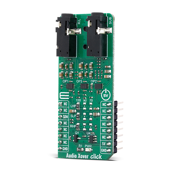
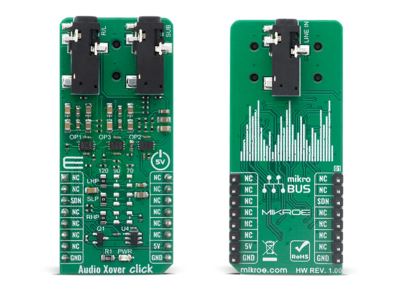
Audio Xover Click is an analog active crossover solution for two-way loudspeakers. The primary purpose of the crossover circuit in a loudspeaker is to split an incoming audio signal into frequency bands that are passed to the speaker or “driver” best suited.

No Abuse Reported

Do you want to subscribe in order to receive notifications regarding "Audio Xover click" changes.

Do you want to unsubscribe in order to stop receiving notifications regarding "Audio Xover click" changes.

Do you want to report abuse regarding "Audio Xover click".

  • mikroSDK Library 2.0.0.0
  • Comments (0)
DOWNLOAD LINK RELATED COMPILER CONTAINS
mikroBasic PRO for ARM
  • lib
  • src
  • exa
  • hlp
  • hex
  • sch
  • pcb
  • doc
mikroBasic PRO for AVR
  • lib
  • src
  • exa
  • hlp
  • hex
  • sch
  • pcb
  • doc
mikroBasic PRO for dsPIC30/33 & PIC24
  • lib
  • src
  • exa
  • hlp
  • hex
  • sch
  • pcb
  • doc
mikroBasic PRO for FT90x
  • lib
  • src
  • exa
  • hlp
  • hex
  • sch
  • pcb
  • doc
mikroBasic PRO for PIC
  • lib
  • src
  • exa
  • hlp
  • hex
  • sch
  • pcb
  • doc
mikroBasic PRO for PIC32
  • lib
  • src
  • exa
  • hlp
  • hex
  • sch
  • pcb
  • doc
mikroC PRO for ARM
  • lib
  • src
  • exa
  • hlp
  • hex
  • sch
  • pcb
  • doc
mikroC PRO for AVR
  • lib
  • src
  • exa
  • hlp
  • hex
  • sch
  • pcb
  • doc
mikroC PRO for dsPIC30/33 & PIC24
  • lib
  • src
  • exa
  • hlp
  • hex
  • sch
  • pcb
  • doc
mikroC PRO for FT90x
  • lib
  • src
  • exa
  • hlp
  • hex
  • sch
  • pcb
  • doc
mikroC PRO for PIC
  • lib
  • src
  • exa
  • hlp
  • hex
  • sch
  • pcb
  • doc
mikroC PRO for PIC32
  • lib
  • src
  • exa
  • hlp
  • hex
  • sch
  • pcb
  • doc
mikroPascal PRO for ARM
  • lib
  • src
  • exa
  • hlp
  • hex
  • sch
  • pcb
  • doc
mikroPascal PRO for AVR
  • lib
  • src
  • exa
  • hlp
  • hex
  • sch
  • pcb
  • doc
mikroPascal PRO for dsPIC30/33 & PIC24
  • lib
  • src
  • exa
  • hlp
  • hex
  • sch
  • pcb
  • doc
mikroPascal PRO for FT90x
  • lib
  • src
  • exa
  • hlp
  • hex
  • sch
  • pcb
  • doc
mikroPascal PRO for PIC
  • lib
  • src
  • exa
  • hlp
  • hex
  • sch
  • pcb
  • doc
mikroPascal PRO for PIC32
  • lib
  • src
  • exa
  • hlp
  • hex
  • sch
  • pcb
  • doc

mikroSDK Library Blog

Audio Xover Click

Audio Xover Click

Native view of the Audio Xover Click board.

View full image
Audio Xover Click

Audio Xover Click

Front and back view of the Audio Xover Click board.

View full image

Library Description

Library contains function for enable and disable module.

Key functions:

  • void audioxover_set_mode( uint8_t state ) - This function set CS pin on 1 ( ENABLE ) and 0 ( DISABLE )

Examples description

The application is composed of three sections :

  • System Initialization - Initializes all necessary GPIO pins
  • Application Initialization - Initializes driver init
  • Application Task - Enable and disable module every one seconds.
void application_task ( )
{
    mikrobus_logWrite( "***ENABLE****", _LOG_LINE );
    audioxover_set_mode( AUDIOXOVER_ENABLE );
    Delay_ms( 3000 );
    mikrobus_logWrite( "***DISABLE****", _LOG_LINE );
    audioxover_set_mode( AUDIOXOVER_DISABLE );
    Delay_ms( 3000 );
}

Other mikroE Libraries used in the example:

  • UART

Additional notes and informations

Depending on the development board you are using, you may need USB UART clickUSB UART 2 click or RS232 click to connect to your PC, for development systems with no UART to USB interface available on the board. The terminal available in all MikroElektronika compilers, or any other terminal application of your choice, can be used to read the message.

ALSO FROM THIS AUTHOR

MCP2003B Click library

3

MCP2003B click is a mikroBUS add-on board with a bi-directional LIN transceiver. The click has three onboard screw terminals for connecting the transceiver to a LIN network (three wires: LIN, VBB and GND). MCP2003B click communicates with the target board MCU through the mikroBUS UART interface (RXD, TXD).

[Learn More]

RF Meter 3 Click

0

RF Meter 3 Click is a compact add-on board that collects information, analyzes RF power, and displays information in an easy-to-read digital format. This board features the LT5581, a low-power monolithic precision RMS power detector from Analog Devices. The RMS detector uses a proprietary technique to accurately measure the RF power in a range from 2GHz up to 2.6GHz, well-suited for signals with high crest factors. It outputs a DC voltage in linear scale proportional to an RF input signal power in dBm.

[Learn More]

DIGI POT 9 Click

0

DIGI POT 9 Click is a compact add-on board used as a digitally controlled potentiometer. This board features the AD5235, a dual-channel, nonvolatile memory, digitally controlled potentiometer from Analog Devices. The AD5235's versatile programming via an SPI-compatible serial interface allows multiple modes of operation and adjustment. The resistor wiper position is determined by the RDAC register contents, which act as a scratchpad register, allowing unlimited changes of resistance settings. The nominal resistance of the RDAC between terminal A and terminal B (RAB) is 250 kΩ with 1024 positions (10-bit resolution).

[Learn More]