TOP Contributors

  1. MIKROE (2784 codes)
  2. Alcides Ramos (402 codes)
  3. Shawon Shahryiar (307 codes)
  4. jm_palomino (129 codes)
  5. Bugz Bensce (97 codes)
  6. S P (73 codes)
  7. dany (71 codes)
  8. MikroBUS.NET Team (35 codes)
  9. NART SCHINACKOW (34 codes)
  10. Armstrong Subero (27 codes)

Most Downloaded

  1. Timer Calculator (140775 times)
  2. FAT32 Library (73360 times)
  3. Network Ethernet Library (58201 times)
  4. USB Device Library (48386 times)
  5. Network WiFi Library (43981 times)
  6. FT800 Library (43538 times)
  7. GSM click (30471 times)
  8. mikroSDK (29176 times)
  9. PID Library (27173 times)
  10. microSD click (26848 times)
Libstock prefers package manager

Package Manager

We strongly encourage users to use Package manager for sharing their code on Libstock website, because it boosts your efficiency and leaves the end user with no room for error. [more info]

< Back
mikroSDK Library

VCP Monitor 2 click

Rating:

5

Author: MIKROE

Last Updated: 2020-06-17

Package Version: 1.0.0.0

mikroSDK Library: 1.0.0.0

Category: Current sensor

Downloaded: 3222 times

Not followed.

License: MIT license  

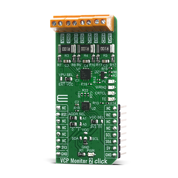
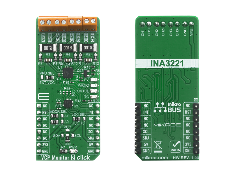
VCP Monitor 2 Click is a three-channel, high-side current and bus voltage monitor with alert indication function ensuring the intended application works within desired operating conditions.

No Abuse Reported

Do you want to subscribe in order to receive notifications regarding "VCP Monitor 2 click" changes.

Do you want to unsubscribe in order to stop receiving notifications regarding "VCP Monitor 2 click" changes.

Do you want to report abuse regarding "VCP Monitor 2 click".

  • mikroSDK Library 2.0.0.0
  • Comments (0)
DOWNLOAD LINK RELATED COMPILER CONTAINS
mikroBasic PRO for ARM
  • lib
  • src
  • exa
  • hlp
  • hex
  • sch
  • pcb
  • doc
mikroBasic PRO for AVR
  • lib
  • src
  • exa
  • hlp
  • hex
  • sch
  • pcb
  • doc
mikroBasic PRO for dsPIC30/33 & PIC24
  • lib
  • src
  • exa
  • hlp
  • hex
  • sch
  • pcb
  • doc
mikroBasic PRO for FT90x
  • lib
  • src
  • exa
  • hlp
  • hex
  • sch
  • pcb
  • doc
mikroBasic PRO for PIC
  • lib
  • src
  • exa
  • hlp
  • hex
  • sch
  • pcb
  • doc
mikroBasic PRO for PIC32
  • lib
  • src
  • exa
  • hlp
  • hex
  • sch
  • pcb
  • doc
mikroC PRO for ARM
  • lib
  • src
  • exa
  • hlp
  • hex
  • sch
  • pcb
  • doc
mikroC PRO for AVR
  • lib
  • src
  • exa
  • hlp
  • hex
  • sch
  • pcb
  • doc
mikroC PRO for dsPIC30/33 & PIC24
  • lib
  • src
  • exa
  • hlp
  • hex
  • sch
  • pcb
  • doc
mikroC PRO for FT90x
  • lib
  • src
  • exa
  • hlp
  • hex
  • sch
  • pcb
  • doc
mikroC PRO for PIC
  • lib
  • src
  • exa
  • hlp
  • hex
  • sch
  • pcb
  • doc
mikroC PRO for PIC32
  • lib
  • src
  • exa
  • hlp
  • hex
  • sch
  • pcb
  • doc
mikroPascal PRO for ARM
  • lib
  • src
  • exa
  • hlp
  • hex
  • sch
  • pcb
  • doc
mikroPascal PRO for AVR
  • lib
  • src
  • exa
  • hlp
  • hex
  • sch
  • pcb
  • doc
mikroPascal PRO for dsPIC30/33 & PIC24
  • lib
  • src
  • exa
  • hlp
  • hex
  • sch
  • pcb
  • doc
mikroPascal PRO for FT90x
  • lib
  • src
  • exa
  • hlp
  • hex
  • sch
  • pcb
  • doc
mikroPascal PRO for PIC
  • lib
  • src
  • exa
  • hlp
  • hex
  • sch
  • pcb
  • doc
mikroPascal PRO for PIC32
  • lib
  • src
  • exa
  • hlp
  • hex
  • sch
  • pcb
  • doc

mikroSDK Library Blog

VCP Monitor 2 Click

VCP Monitor 2 Click

Native view of the VCP Monitor 2 Click board.

View full image
VCP Monitor 2 Click

VCP Monitor 2 Click

Front and back view of the VCP Monitor 2 Click board.

View full image

Library Description

The library contains basic communication with the module and allows the user to read and write data to the module. The user can read the current data of current, voltage and power measured by the sensor.

Key functions:

  • float vcpmonitor2_get_shunt_voltage ( uint8_t channel ) - Get Shunt voltage in mV
  • float vcpmonitor2_get_current ( uint8_t channel ) - Get Current data in mA
  • float vcpmonitor2_get_power ( uint8_t channel ) - Get Power in W

Examples description

The application is composed of three sections :

  • System Initialization - Initialization I2C module and RST pin on OUTPUT
  • Application Initialization - Initiaization driver init, device configuration for measurement, alert status reset and configuration
  • Application Task - Display Voltage on the BUS and Shunt, current and power data. Display Alert status informations.
void application_task ( )
{
    mikrobus_logWrite( ">> CHANNEL 1 <<", _LOG_LINE );
    display_channel_data( VCPMONITOR2_CHANNEL_1 );
    mikrobus_logWrite( ">> CHANNEL 2 <<", _LOG_LINE );
    display_channel_data( VCPMONITOR2_CHANNEL_2 );
    mikrobus_logWrite( ">> CHANNEL 3 <<", _LOG_LINE );
    display_channel_data( VCPMONITOR2_CHANNEL_3 );
    display_alert_status( );
    mikrobus_logWrite( "---------------------", _LOG_LINE );
    Delay_ms( 4000 );
}


Additional Functions :

  • display_alert_status() - Alert status
  • display_channel_data() - Channel data

Other mikroE Libraries used in the example:

  • I2C Library
  • UART Library

Additional notes and informations

Depending on the development board you are using, you may need USB UART clickUSB UART 2 click or RS232 click to connect to your PC, for development systems with no UART to USB interface available on the board. The terminal available in all MikroElektronika compilers, or any other terminal application of your choice, can be used to read the message.

ALSO FROM THIS AUTHOR

MCP251863 Click

0

MCP251863 Click is a compact add-on board representing a complete CAN solution used as a control node in a CAN network. This board features the MCP251863, IC representing a compact solution with a controller and a transceiver in one package, the MCP2518FD and ATA6563 from Microchip. The ATA6563, a low-level physical layer IC (PHY), provides a physical connection with the CAN bus itself, while the CAN controller MCP2518FD represents an interface between the MCU and the PHY. It features three operating modes with dedicated fail-safe features, remote wake-up via CAN, and ideally passive behavior when powered off on the CAN bus. This Click board™ is suitable for developing a wide range of automotive diagnostic applications, even on MCUs that don’t support CAN interface.

[Learn More]

2x5W Amp click

6

2x5W AMP click functions as an amplifier and features the TDA7491LP 2x5-watt dual BTL class-D audio amplifier. The click is designed to run on either 3.3V or 5V power supply. It communicates with the target MCU over the following pins on the mikroBUSâ„¢ line: AN, RST, CS, PWM, INT.

[Learn More]

Thermo 29 Click

0

Thermo 29 Click is a compact add-on board for accurate temperature measurements. This board features the TMP126, a high-accuracy SPI-configurable digital temperature sensor from Texas Instruments. The TMP126 consists of an internal thermal BJT factory-calibrated sensor, 14-bit ADC, and a digital signal processor, offering a high accuracy of ±0.25°C and a temperature resolution of 0.03125°C per LSB. It also has a programmable alarm function that outputs an interrupt signal to the MCU when a specific temperature event occurs.

[Learn More]