We strongly encourage users to use Package manager for sharing their code on Libstock website, because it boosts your efficiency and leaves the end user with no room for error. [more info]

Rating:
Author: MIKROE
Last Updated: 2020-10-19
Package Version: 1.0.0.0
mikroSDK Library: 1.0.0.0
Category: Motion
Downloaded: 600 times
Not followed.
License: MIT license
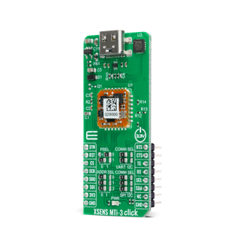
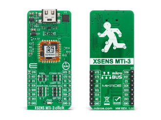
XSENS MTi-3 Click is a compact add-on board that contains a fully functional module that can be configured as an Inertial Measurement Unit, Vertical reference Unit, or even an Attitude & Heading Reference System.
Do you want to subscribe in order to receive notifications regarding "XSENS MTI-3 click" changes.
Do you want to unsubscribe in order to stop receiving notifications regarding "XSENS MTI-3 click" changes.
Do you want to report abuse regarding "XSENS MTI-3 click".
| DOWNLOAD LINK | RELATED COMPILER | CONTAINS |
|---|---|---|
| 1589971987_xsens_mti_3_clic_mikrobasic_arm.mpkg [695.75KB] | mikroBasic PRO for ARM |
|
| 1589972010_xsens_mti_3_clic_mikroc_arm.mpkg [809.94KB] | mikroC PRO for ARM |
|
| 1589972027_xsens_mti_3_clic_mikropascal_arm.mpkg [695.59KB] | mikroPascal PRO for ARM |
|


Library Description
The library contains basic functions for working with click. Of the communications, only UART is supported.
Key functions:
void xsensmti3_parser(uint8_t *rsp_buf, uint8_t start_cnt xsensmti3_parse_t *obj ) - General Parservoid xsensmti3_get_data(xsensmti3_quat_t *quat_obj,xsensmti3_data_t *data_obj) - Get Roll, Pitch and Yawuint8_t xsensmti3_check_package(uint8_t *package_buf,uint8_t *start_package) - Checks packageExamples description
The application is composed of three sections :
void application_task ( )
{
    uint8_t check_data = 0;
    uint8_t cnt = 0;

    // STARTS COLLECTING DATA
    if ( active_flag == XSENSMTI3_WAIT_FOR_START )
    {
        memset( &parser_current_buf[0], 0 , 110 );
        parser_buf_cnt = 0;
        active_flag = XSENSMTI3_START_PROCESS;
        xsensmti3_enable_uart_isr( );
    }

    // CHECKS RECEIVED DATA
    if ( ( parser_buf_cnt > 100 ) && ( active_flag == XSENSMTI3_START_PROCESS ) )
    {
       xsensmti3_disable_uart_isr( );
       active_flag = XSENSMTI3_DATA_PROCESSING;
    }

    // CHECKS IF THE VALID PACKAGE IS RECEIVED
    if ( active_flag == XSENSMTI3_DATA_PROCESSING )
    {
        check_data = xsensmti3_check_package( &parser_current_buf[0], &start_rsp );
        if ( check_data == 1 )
        {
            active_flag = XSENSMTI3_PARSER_DATA;
        }
        else
        {
            active_flag = XSENSMTI3_WAIT_FOR_START;
        }
    }

    // PARSING DATA AND DISPLAY
    if ( active_flag == XSENSMTI3_PARSER_DATA )
    {
       xsensmti3_parser( &parser_current_buf[0], start_rsp, &parse_data_obj );

       mikrobus_logWrite( ">> Quaternion data <<", _LOG_LINE );

       for ( cnt = 0; cnt < 4; cnt++ )
       {
           mikrobus_logWrite( ">> Q: ", _LOG_TEXT );
           FloatToStr( parse_data_obj.quat_obj.quat_data[ cnt ], demo_text );
           LTrim( demo_text );
           mikrobus_logWrite( demo_text , _LOG_LINE );
       }

       mikrobus_logWrite( "--------------", _LOG_LINE );

       xsensmti3_get_data( &parse_data_obj.quat_obj, &data_obj );

       mikrobus_logWrite( ">> ROLL: ", _LOG_TEXT );
       FloatToStr( data_obj.roll, demo_text );
       LTrim( demo_text );
       mikrobus_logWrite( demo_text , _LOG_LINE );

       mikrobus_logWrite( ">> PITCH: ", _LOG_TEXT );
       FloatToStr( data_obj.pitch, demo_text );
       LTrim( demo_text );
       mikrobus_logWrite( demo_text , _LOG_LINE );

       mikrobus_logWrite( ">> YAW: ", _LOG_TEXT );
       FloatToStr( data_obj.yaw, demo_text );
       LTrim( demo_text );
       mikrobus_logWrite( demo_text , _LOG_LINE );

       Delay_ms( 1000 );
       active_flag = XSENSMTI3_WAIT_FOR_START;

       mikrobus_logWrite( " rn--------------", _LOG_LINE );
    }
}
Other mikroE Libraries used in the example:
Additional notes and informations
Depending on the development board you are using, you may need USB UART click, USB UART 2 click or RS232 click to connect to your PC, for development systems with no UART to USB interface available on the board. The terminal available in all MikroElektronika compilers, or any other terminal application of your choice, can be used to read the message.