TOP Contributors

  1. MIKROE (2779 codes)
  2. Alcides Ramos (376 codes)
  3. Shawon Shahryiar (307 codes)
  4. jm_palomino (118 codes)
  5. Bugz Bensce (97 codes)
  6. S P (73 codes)
  7. dany (71 codes)
  8. MikroBUS.NET Team (35 codes)
  9. NART SCHINACKOW (34 codes)
  10. Armstrong Subero (27 codes)

Most Downloaded

  1. Timer Calculator (139563 times)
  2. FAT32 Library (72041 times)
  3. Network Ethernet Library (57254 times)
  4. USB Device Library (47615 times)
  5. Network WiFi Library (43219 times)
  6. FT800 Library (42556 times)
  7. GSM click (29930 times)
  8. mikroSDK (28292 times)
  9. PID Library (26930 times)
  10. microSD click (26309 times)
Libstock prefers package manager

Package Manager

We strongly encourage users to use Package manager for sharing their code on Libstock website, because it boosts your efficiency and leaves the end user with no room for error. [more info]

< Back
mikroSDK Library

VCP Monitor 3 click

Rating:

5

Author: MIKROE

Last Updated: 2020-08-05

Package Version: 1.0.0.0

mikroSDK Library: 1.0.0.0

Category: Current sensor

Downloaded: 2017 times

Not followed.

License: MIT license  

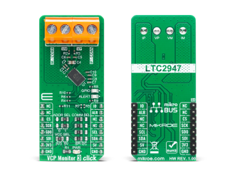
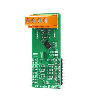
VCP Monitor 3 Click is a high precision Voltage, Current and Power measurement Click board with an input capable of taking up to 15V. It features the LTC2947, from Analog Devices, a high precision power and energy monitor with an internal sense resistor supporting up to ±30A.

No Abuse Reported

Do you want to subscribe in order to receive notifications regarding "VCP Monitor 3 click" changes.

Do you want to unsubscribe in order to stop receiving notifications regarding "VCP Monitor 3 click" changes.

Do you want to report abuse regarding "VCP Monitor 3 click".
  • mikroSDK Library 2.0.0.0
  • Comments (0)
DOWNLOAD LINK RELATED COMPILER CONTAINS
mikroBasic PRO for ARM
  • lib
  • src
  • exa
  • hlp
  • hex
  • sch
  • pcb
  • doc
mikroBasic PRO for AVR
  • lib
  • src
  • exa
  • hlp
  • hex
  • sch
  • pcb
  • doc
mikroBasic PRO for dsPIC30/33 & PIC24
  • lib
  • src
  • exa
  • hlp
  • hex
  • sch
  • pcb
  • doc
mikroBasic PRO for FT90x
  • lib
  • src
  • exa
  • hlp
  • hex
  • sch
  • pcb
  • doc
mikroBasic PRO for PIC
  • lib
  • src
  • exa
  • hlp
  • hex
  • sch
  • pcb
  • doc
mikroBasic PRO for PIC32
  • lib
  • src
  • exa
  • hlp
  • hex
  • sch
  • pcb
  • doc
mikroC PRO for ARM
  • lib
  • src
  • exa
  • hlp
  • hex
  • sch
  • pcb
  • doc
mikroC PRO for AVR
  • lib
  • src
  • exa
  • hlp
  • hex
  • sch
  • pcb
  • doc
mikroC PRO for dsPIC30/33 & PIC24
  • lib
  • src
  • exa
  • hlp
  • hex
  • sch
  • pcb
  • doc
mikroC PRO for FT90x
  • lib
  • src
  • exa
  • hlp
  • hex
  • sch
  • pcb
  • doc
mikroC PRO for PIC
  • lib
  • src
  • exa
  • hlp
  • hex
  • sch
  • pcb
  • doc
mikroC PRO for PIC32
  • lib
  • src
  • exa
  • hlp
  • hex
  • sch
  • pcb
  • doc
mikroPascal PRO for ARM
  • lib
  • src
  • exa
  • hlp
  • hex
  • sch
  • pcb
  • doc
mikroPascal PRO for AVR
  • lib
  • src
  • exa
  • hlp
  • hex
  • sch
  • pcb
  • doc
mikroPascal PRO for dsPIC30/33 & PIC24
  • lib
  • src
  • exa
  • hlp
  • hex
  • sch
  • pcb
  • doc
mikroPascal PRO for FT90x
  • lib
  • src
  • exa
  • hlp
  • hex
  • sch
  • pcb
  • doc
mikroPascal PRO for PIC
  • lib
  • src
  • exa
  • hlp
  • hex
  • sch
  • pcb
  • doc
mikroPascal PRO for PIC32
  • lib
  • src
  • exa
  • hlp
  • hex
  • sch
  • pcb
  • doc

mikroSDK Library Blog

VCP Monitor 3 Click

VCP Monitor 3 Click

Native view of the VCP Monitor 3 Click board.

View full image
VCP Monitor 3 Click

VCP Monitor 3 Click

Front and back view of the VCP Monitor 3 Click board.

View full image

Library Description

The library covers all the functions necessary to control VCP Monitor 3 click board. It initializes and defines the SPI and I2C bus drivers, and holds functions that allow full control of the device to the user. User can change operation mode, read: current, power, voltage, VCC voltage, energy, charge and base time. User can also use various read and write functions.

Key functions:

  • float vcpmonitor3_read_i ( ); - Function is used to get current in Amperes.
  • float vcpmonitor3_read_p ( ); - Function is used to get power in Watts.
  • float vcpmonitor3_read_v ( ); - Function is used to get voltage in Volts.

Examples description

The application is composed of three sections :

  • System Initialization - Initializes I2C and LOG, and sets CS and PWM pins as output and INT pin as input.
  • Application Initialization - Initalizes I2C driver and sets up the device.
  • Application Task - This example shows capabilities of VCP Monitor 3 Click board by reading current, voltage, power, die temperature and voltage at DVCC and displaying the results via USART terminal.
void application_task( )
{
    float cur_data;
    float volt_data;
    float pow_data;
    float die_temp;
    float volt_vcc;

    cur_data = vcpmonitor3_read_i(  );
    FloatToStr( cur_data, log_txt );
    mikrobus_logWrite( "Current : ", _LOG_TEXT );
    mikrobus_logWrite( log_txt, _LOG_TEXT );
    mikrobus_logWrite( " A", _LOG_LINE );

    pow_data = vcpmonitor3_read_p(  );
    FloatToStr( pow_data, log_txt );
    mikrobus_logWrite( "Power : ", _LOG_TEXT );
    mikrobus_logWrite( log_txt, _LOG_TEXT );
    mikrobus_logWrite( " W", _LOG_LINE );

    volt_data = vcpmonitor3_read_v(  );
    FloatToStr( volt_data, log_txt );
    mikrobus_logWrite( "Voltage : ", _LOG_TEXT );
    mikrobus_logWrite( log_txt, _LOG_TEXT );
    mikrobus_logWrite( " V", _LOG_LINE );

    die_temp = vcpmonitor3_read_temp(  );
    FloatToStr( die_temp, log_txt );
    mikrobus_logWrite( "Die Temperature : ", _LOG_TEXT );
    mikrobus_logWrite( log_txt, _LOG_TEXT );
    mikrobus_logWrite( deg_cel, _LOG_LINE );

    volt_vcc = vcpmonitor3_read_vcc(  );
    FloatToStr( volt_vcc, log_txt );
    mikrobus_logWrite( "Voltage at DVCC : ", _LOG_TEXT );
    mikrobus_logWrite( log_txt, _LOG_TEXT );
    mikrobus_logWrite( " V", _LOG_LINE );

    mikrobus_logWrite( " ------------------------------- ", _LOG_LINE );
    Delay_ms( 1000 );
}

Other mikroE Libraries used in the example:

  • I2C
  • SPI
  • UART
  • Conversions

Additional notes and informations

Depending on the development board you are using, you may need USB UART clickUSB UART 2 click or RS232 click to connect to your PC, for development systems with no UART to USB interface available on the board. The terminal available in all MikroElektronika compilers, or any other terminal application of your choice, can be used to read the message.

ALSO FROM THIS AUTHOR

ISO ADC Click

0

The ISO ADC Click is add-on board current-shunt measurement device with isolated delta-sigma modulator. This Click board™ is based on AMC1204BDWR provide a single-chip solution for measuring the small signal of a shunt resistor across an isolated barrier from Texas Instruments. ISO ADC Click contains shunt resistor, these types of resistors are typically used to sense currents in motor control inverters, green energy generation systems, and other industrial applications.

[Learn More]

Accel 15 Click

0

Accel 15 Click is a compact add-on board that contains a longevity acceleration sensor. This board features the BMA490L, a high-performance 16-bit digital triaxial acceleration sensor with extended availability of up to ten years from Bosch Sensortech. It allows selectable full-scale acceleration measurements in ranges of ±2g, ±4g, ±8g, and ±16g in three axes with a configurable host interface that supports both I2C and SPI serial communication and with intelligent on-chip motion-triggered interrupt features. Intelligent signal processing and evaluation in the accelerometer ASIC enables advanced gesture recognition for numerous industrial IoT applications where low power consumption is vital. This Click board™ is suitable for home appliances, power tools, and other industrial products whose lifetime is essential.

[Learn More]

DHT22 2 Click

0

DHT22 2 Click is used for measuring the environmental temperature and relative humidity. It uses the AM2322 sensor, with very accurate thermal and humidity measuring capabilities. It can use either 1-Wire or I2C protocol to communicate with the integrated circuit.

[Learn More]