TOP Contributors

  1. MIKROE (2784 codes)
  2. Alcides Ramos (405 codes)
  3. Shawon Shahryiar (307 codes)
  4. jm_palomino (133 codes)
  5. Bugz Bensce (97 codes)
  6. S P (73 codes)
  7. dany (71 codes)
  8. MikroBUS.NET Team (35 codes)
  9. NART SCHINACKOW (34 codes)
  10. Armstrong Subero (27 codes)

Most Downloaded

  1. Timer Calculator (142069 times)
  2. FAT32 Library (75295 times)
  3. Network Ethernet Library (59492 times)
  4. USB Device Library (49524 times)
  5. Network WiFi Library (45288 times)
  6. FT800 Library (44915 times)
  7. GSM click (31432 times)
  8. mikroSDK (30452 times)
  9. microSD click (27802 times)
  10. PID Library (27624 times)
Libstock prefers package manager

Package Manager

We strongly encourage users to use Package manager for sharing their code on Libstock website, because it boosts your efficiency and leaves the end user with no room for error. [more info]

< Back
mikroSDK Library

VCP Monitor 3 click

Rating:

5

Author: MIKROE

Last Updated: 2020-08-05

Package Version: 1.0.0.0

mikroSDK Library: 1.0.0.0

Category: Current sensor

Downloaded: 2925 times

Not followed.

License: MIT license  

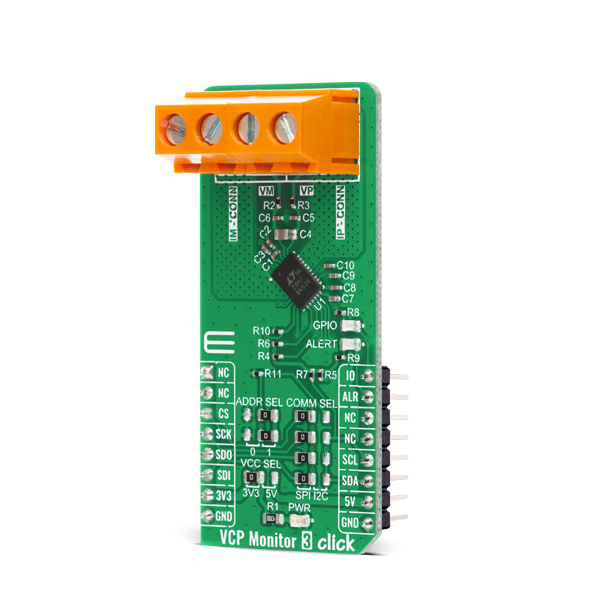
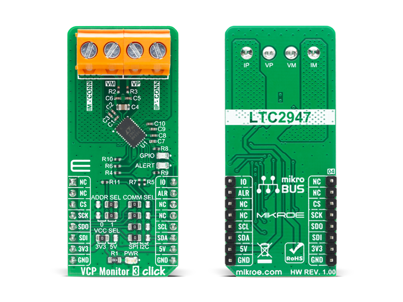
VCP Monitor 3 Click is a high precision Voltage, Current and Power measurement Click board with an input capable of taking up to 15V. It features the LTC2947, from Analog Devices, a high precision power and energy monitor with an internal sense resistor supporting up to ±30A.

No Abuse Reported

Do you want to subscribe in order to receive notifications regarding "VCP Monitor 3 click" changes.

Do you want to unsubscribe in order to stop receiving notifications regarding "VCP Monitor 3 click" changes.

Do you want to report abuse regarding "VCP Monitor 3 click".

  • mikroSDK Library 2.0.0.0
  • Comments (0)
DOWNLOAD LINK RELATED COMPILER CONTAINS
mikroBasic PRO for ARM
  • lib
  • src
  • exa
  • hlp
  • hex
  • sch
  • pcb
  • doc
mikroBasic PRO for AVR
  • lib
  • src
  • exa
  • hlp
  • hex
  • sch
  • pcb
  • doc
mikroBasic PRO for dsPIC30/33 & PIC24
  • lib
  • src
  • exa
  • hlp
  • hex
  • sch
  • pcb
  • doc
mikroBasic PRO for FT90x
  • lib
  • src
  • exa
  • hlp
  • hex
  • sch
  • pcb
  • doc
mikroBasic PRO for PIC
  • lib
  • src
  • exa
  • hlp
  • hex
  • sch
  • pcb
  • doc
mikroBasic PRO for PIC32
  • lib
  • src
  • exa
  • hlp
  • hex
  • sch
  • pcb
  • doc
mikroC PRO for ARM
  • lib
  • src
  • exa
  • hlp
  • hex
  • sch
  • pcb
  • doc
mikroC PRO for AVR
  • lib
  • src
  • exa
  • hlp
  • hex
  • sch
  • pcb
  • doc
mikroC PRO for dsPIC30/33 & PIC24
  • lib
  • src
  • exa
  • hlp
  • hex
  • sch
  • pcb
  • doc
mikroC PRO for FT90x
  • lib
  • src
  • exa
  • hlp
  • hex
  • sch
  • pcb
  • doc
mikroC PRO for PIC
  • lib
  • src
  • exa
  • hlp
  • hex
  • sch
  • pcb
  • doc
mikroC PRO for PIC32
  • lib
  • src
  • exa
  • hlp
  • hex
  • sch
  • pcb
  • doc
mikroPascal PRO for ARM
  • lib
  • src
  • exa
  • hlp
  • hex
  • sch
  • pcb
  • doc
mikroPascal PRO for AVR
  • lib
  • src
  • exa
  • hlp
  • hex
  • sch
  • pcb
  • doc
mikroPascal PRO for dsPIC30/33 & PIC24
  • lib
  • src
  • exa
  • hlp
  • hex
  • sch
  • pcb
  • doc
mikroPascal PRO for FT90x
  • lib
  • src
  • exa
  • hlp
  • hex
  • sch
  • pcb
  • doc
mikroPascal PRO for PIC
  • lib
  • src
  • exa
  • hlp
  • hex
  • sch
  • pcb
  • doc
mikroPascal PRO for PIC32
  • lib
  • src
  • exa
  • hlp
  • hex
  • sch
  • pcb
  • doc

mikroSDK Library Blog

VCP Monitor 3 Click

VCP Monitor 3 Click

Native view of the VCP Monitor 3 Click board.

View full image
VCP Monitor 3 Click

VCP Monitor 3 Click

Front and back view of the VCP Monitor 3 Click board.

View full image

Library Description

The library covers all the functions necessary to control VCP Monitor 3 click board. It initializes and defines the SPI and I2C bus drivers, and holds functions that allow full control of the device to the user. User can change operation mode, read: current, power, voltage, VCC voltage, energy, charge and base time. User can also use various read and write functions.

Key functions:

  • float vcpmonitor3_read_i ( ); - Function is used to get current in Amperes.
  • float vcpmonitor3_read_p ( ); - Function is used to get power in Watts.
  • float vcpmonitor3_read_v ( ); - Function is used to get voltage in Volts.

Examples description

The application is composed of three sections :

  • System Initialization - Initializes I2C and LOG, and sets CS and PWM pins as output and INT pin as input.
  • Application Initialization - Initalizes I2C driver and sets up the device.
  • Application Task - This example shows capabilities of VCP Monitor 3 Click board by reading current, voltage, power, die temperature and voltage at DVCC and displaying the results via USART terminal.
void application_task( )
{
    float cur_data;
    float volt_data;
    float pow_data;
    float die_temp;
    float volt_vcc;

    cur_data = vcpmonitor3_read_i(  );
    FloatToStr( cur_data, log_txt );
    mikrobus_logWrite( "Current : ", _LOG_TEXT );
    mikrobus_logWrite( log_txt, _LOG_TEXT );
    mikrobus_logWrite( " A", _LOG_LINE );

    pow_data = vcpmonitor3_read_p(  );
    FloatToStr( pow_data, log_txt );
    mikrobus_logWrite( "Power : ", _LOG_TEXT );
    mikrobus_logWrite( log_txt, _LOG_TEXT );
    mikrobus_logWrite( " W", _LOG_LINE );

    volt_data = vcpmonitor3_read_v(  );
    FloatToStr( volt_data, log_txt );
    mikrobus_logWrite( "Voltage : ", _LOG_TEXT );
    mikrobus_logWrite( log_txt, _LOG_TEXT );
    mikrobus_logWrite( " V", _LOG_LINE );

    die_temp = vcpmonitor3_read_temp(  );
    FloatToStr( die_temp, log_txt );
    mikrobus_logWrite( "Die Temperature : ", _LOG_TEXT );
    mikrobus_logWrite( log_txt, _LOG_TEXT );
    mikrobus_logWrite( deg_cel, _LOG_LINE );

    volt_vcc = vcpmonitor3_read_vcc(  );
    FloatToStr( volt_vcc, log_txt );
    mikrobus_logWrite( "Voltage at DVCC : ", _LOG_TEXT );
    mikrobus_logWrite( log_txt, _LOG_TEXT );
    mikrobus_logWrite( " V", _LOG_LINE );

    mikrobus_logWrite( " ------------------------------- ", _LOG_LINE );
    Delay_ms( 1000 );
}

Other mikroE Libraries used in the example:

  • I2C
  • SPI
  • UART
  • Conversions

Additional notes and informations

Depending on the development board you are using, you may need USB UART clickUSB UART 2 click or RS232 click to connect to your PC, for development systems with no UART to USB interface available on the board. The terminal available in all MikroElektronika compilers, or any other terminal application of your choice, can be used to read the message.

ALSO FROM THIS AUTHOR

ADC 20 Click

0

ADC 20 Click is a compact add-on board with a high-performance data converter. This board features the TLA2518, an SPI-configurable eight-channel 12-bit successive approximation register analog-to-digital converter (SAR ADC) from Texas Instruments. The TLA2518 has an internal oscillator for the ADC conversion and supports averaging multiple data samples with a single conversion start. Also, the built-in programmable averaging filters help reduce noise from the analog inputs and reduce the number of data samples required to be read by the host MCU. All eight channels can be used as analog inputs, with the addition that the four channels can be used as digital inputs or digital outputs.

[Learn More]

Mic click

0

Mic click carries the SPQ0410HR5H-B surface mount silicon microphone with maximum RF protection. The click is designed to run on a 3.3V power supply. It communicates with the target microcontroller over the AN pin on the mikroBUSâ„¢ line.

[Learn More]

Heart Rate 7 click

5

Heart Rate 7 click is an optical biosensor Click board which can be used for heart-rate monitoring (HRM). This Click board employs a very sensitive analog front-end IC with high dynamic range, which ensures accurate and reliable readings.

[Learn More]