TOP Contributors

  1. MIKROE (2663 codes)
  2. Alcides Ramos (358 codes)
  3. Shawon Shahryiar (307 codes)
  4. jm_palomino (112 codes)
  5. Chisanga Mumba (90 codes)
  6. S P (73 codes)
  7. dany (71 codes)
  8. MikroBUS.NET Team (35 codes)
  9. NART SCHINACKOW (34 codes)
  10. Armstrong Subero (27 codes)

Most Downloaded

  1. Timer Calculator (137103 times)
  2. FAT32 Library (70236 times)
  3. Network Ethernet Library (56126 times)
  4. USB Device Library (46434 times)
  5. Network WiFi Library (42079 times)
  6. FT800 Library (41389 times)
  7. GSM click (29118 times)
  8. mikroSDK (26564 times)
  9. PID Library (26503 times)
  10. microSD click (25487 times)
Libstock prefers package manager

Package Manager

We strongly encourage users to use Package manager for sharing their code on Libstock website, because it boosts your efficiency and leaves the end user with no room for error. [more info]

< Back
mikroSDK Library

AN to PWM 2 click

Rating:

5

Author: MIKROE

Last Updated: 2020-08-31

Package Version: 1.0.0.0

mikroSDK Library: 1.0.0.0

Category: ADC

Downloaded: 1641 times

Not followed.

License: MIT license  

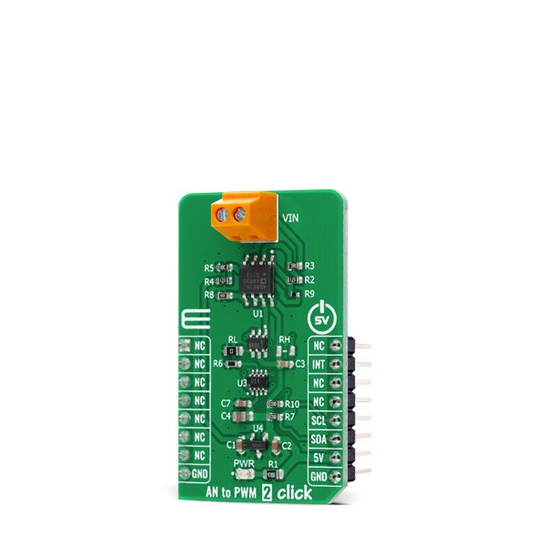
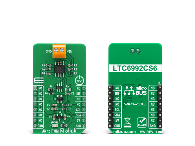
AN to PWM 2 Click is a compact add-on board that contains an easy-to-use component that converts the value of the input analog signal to a fixed frequency PWM voltage output, with a duty cycle proportional to the input voltage.

No Abuse Reported

Do you want to subscribe in order to receive notifications regarding "AN to PWM 2 click" changes.

Do you want to unsubscribe in order to stop receiving notifications regarding "AN to PWM 2 click" changes.

Do you want to report abuse regarding "AN to PWM 2 click".

  • mikroSDK Library 2.0.0.0
  • Comments (0)
DOWNLOAD LINK RELATED COMPILER CONTAINS
mikroBasic PRO for ARM
  • lib
  • src
  • exa
  • hlp
  • hex
  • sch
  • pcb
  • doc
mikroBasic PRO for AVR
  • lib
  • src
  • exa
  • hlp
  • hex
  • sch
  • pcb
  • doc
mikroBasic PRO for dsPIC30/33 & PIC24
  • lib
  • src
  • exa
  • hlp
  • hex
  • sch
  • pcb
  • doc
mikroBasic PRO for FT90x
  • lib
  • src
  • exa
  • hlp
  • hex
  • sch
  • pcb
  • doc
mikroBasic PRO for PIC
  • lib
  • src
  • exa
  • hlp
  • hex
  • sch
  • pcb
  • doc
mikroBasic PRO for PIC32
  • lib
  • src
  • exa
  • hlp
  • hex
  • sch
  • pcb
  • doc
mikroC PRO for ARM
  • lib
  • src
  • exa
  • hlp
  • hex
  • sch
  • pcb
  • doc
mikroC PRO for AVR
  • lib
  • src
  • exa
  • hlp
  • hex
  • sch
  • pcb
  • doc
mikroC PRO for dsPIC30/33 & PIC24
  • lib
  • src
  • exa
  • hlp
  • hex
  • sch
  • pcb
  • doc
mikroC PRO for FT90x
  • lib
  • src
  • exa
  • hlp
  • hex
  • sch
  • pcb
  • doc
mikroC PRO for PIC
  • lib
  • src
  • exa
  • hlp
  • hex
  • sch
  • pcb
  • doc
mikroC PRO for PIC32
  • lib
  • src
  • exa
  • hlp
  • hex
  • sch
  • pcb
  • doc
mikroPascal PRO for ARM
  • lib
  • src
  • exa
  • hlp
  • hex
  • sch
  • pcb
  • doc
mikroPascal PRO for AVR
  • lib
  • src
  • exa
  • hlp
  • hex
  • sch
  • pcb
  • doc
mikroPascal PRO for dsPIC30/33 & PIC24
  • lib
  • src
  • exa
  • hlp
  • hex
  • sch
  • pcb
  • doc
mikroPascal PRO for FT90x
  • lib
  • src
  • exa
  • hlp
  • hex
  • sch
  • pcb
  • doc
mikroPascal PRO for PIC
  • lib
  • src
  • exa
  • hlp
  • hex
  • sch
  • pcb
  • doc
mikroPascal PRO for PIC32
  • lib
  • src
  • exa
  • hlp
  • hex
  • sch
  • pcb
  • doc

mikroSDK Library Blog

AN to PWM 2 click

AN to PWM 2 click

Native view of the AN to PWM 2 click board.

View full image
AN to PWM 2 click

AN to PWM 2 click

Front and back view of the AN to PWM 2 click board.

View full image

Library Description

The library contains basic function for sets frequency and gets interrupt pin state.

Key functions:

  • uint8_t antopwm2_get_int_state ( void ) - Gets interrupt pin state
  • void antopwm2_set_freq ( uint8_t freq ) - Set Frequency

Examples description

The application is composed of three sections :

  • System Initialization - Initializes the INT pin required to measure.
  • Application Initialization - Initializes the driver, timer on 1us and frequency
  • Application Initialization - Initializes the driver, timer on 1us and frequency
void application_task ( )
{
    uint8_t drdy;
    char rsp_data;

    drdy = UART_Rdy_Ptr( );

    if ( drdy != 0 )
    {
        rsp_data = UART_Rd_Ptr( );

        switch ( rsp_data )
        {
            case '+' :
            {
                // Reset flags
                period_flag = 0;
                idle_high_cnt = 0;
                idle_low_cnt = 0;
                period_cnt = 0;
                    
                while ( period_flag != 1 );
                
                idle_high_cnt /= 10;
                idle_low_cnt /= 10;

                if ( ( idle_high_cnt != 0 ) && ( idle_high_cnt != 0 ) )
                {
                    tmp_value = calc_percentage( idle_high_cnt );
                    FloatToStr( tmp_value, demo_text );
                    mikrobus_logWrite( "> Idle [HIGH]: ~ ", _LOG_TEXT );
                    mikrobus_logWrite( demo_text, _LOG_TEXT );
                    mikrobus_logWrite( " %", _LOG_LINE );

                    tmp_value = calc_percentage( idle_low_cnt );
                    FloatToStr( tmp_value, demo_text );
                    mikrobus_logWrite( "> Idle [LOW]: ~ ", _LOG_TEXT );
                    mikrobus_logWrite( demo_text, _LOG_TEXT );
                    mikrobus_logWrite( " %", _LOG_LINE );

                    tmp_value = calc_voltage( idle_high_cnt );
                    FloatToStr( tmp_value , demo_text );
                    mikrobus_logWrite( "> Voltage: ~ ", _LOG_TEXT );
                    mikrobus_logWrite( demo_text, _LOG_TEXT );
                    mikrobus_logWrite( " mV", _LOG_LINE );

                    mikrobus_logWrite( "--------------------------------", _LOG_LINE );
                }
                mikrobus_logWrite( "--- Please, enter the command [ + ].", _LOG_LINE );
                break;
            }
        }
    }
}

Additional Functions :

  • calc_percentage( ) - Represented data as a percentage
  • calc_voltage( ) - Voltage calculation
  • timer_init_1us( ) - Sets timer on 1us

Other mikroE Libraries used in the example:

  • I2C Library
  • Conersions Library

Additional notes and informations

Depending on the development board you are using, you may need USB UART clickUSB UART 2 click or RS232 click to connect to your PC, for development systems with no UART to USB interface available on the board. The terminal available in all MikroElektronika compilers, or any other terminal application of your choice, can be used to read the message.


ALSO FROM THIS AUTHOR

Hall Switch 3 click

0

Hall Switch 3 Click is a compact add-on board representing a magnetic field-activated switch. This board features the NMH1000, a Hall-effect magnetic switch from NXP Semiconductor. It is a low-voltage, low-current, and low-output data rate device with a very small size. The switch is most sensitive to a vertical field passing through the top-bottom surfaces, orthogonal to the plane of the Hall Switch 3 Click board™.

[Learn More]

DC Motor 29 click

0

DC Motor 29 Click is a compact add-on board that contains a high-performance DC motor driver. This board features the DRV8245P, an automotive H-Bridge driver with integrated current sense and diagnostic from Texas Instruments. It can be configured as a single full-bridge driver or independent half-bridge driver. The driver offers excellent power handling and thermal capability due to a BiCMOS high power process technology mode, in which it is designed.

[Learn More]

CAP WHEEL click

0

This application is use for controling various devices

[Learn More]