TOP Contributors

  1. MIKROE (2784 codes)
  2. Alcides Ramos (405 codes)
  3. Shawon Shahryiar (307 codes)
  4. jm_palomino (133 codes)
  5. Bugz Bensce (97 codes)
  6. S P (73 codes)
  7. dany (71 codes)
  8. MikroBUS.NET Team (35 codes)
  9. NART SCHINACKOW (34 codes)
  10. Armstrong Subero (27 codes)

Most Downloaded

  1. Timer Calculator (141818 times)
  2. FAT32 Library (74953 times)
  3. Network Ethernet Library (59310 times)
  4. USB Device Library (49305 times)
  5. Network WiFi Library (45103 times)
  6. FT800 Library (44672 times)
  7. GSM click (31286 times)
  8. mikroSDK (30210 times)
  9. microSD click (27657 times)
  10. PID Library (27562 times)
Libstock prefers package manager

Package Manager

We strongly encourage users to use Package manager for sharing their code on Libstock website, because it boosts your efficiency and leaves the end user with no room for error. [more info]

< Back
mikroSDK Library

ISO ADC 3 click

Rating:

5

Author: MIKROE

Last Updated: 2020-12-23

Package Version: 1.0.0.0

mikroSDK Library: 1.0.0.0

Category: ADC

Downloaded: 2679 times

Not followed.

License: MIT license  

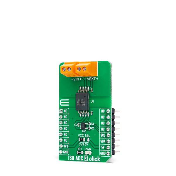
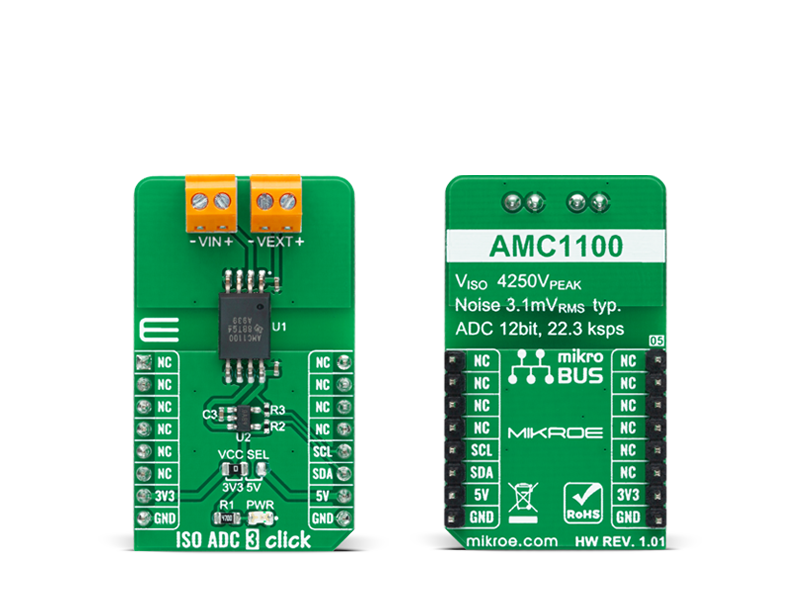
ISO ADC 3 Click is a compact add-on board that contains a single-channel precision isolation amplifier.

No Abuse Reported

Do you want to subscribe in order to receive notifications regarding "ISO ADC 3 click" changes.

Do you want to unsubscribe in order to stop receiving notifications regarding "ISO ADC 3 click" changes.

Do you want to report abuse regarding "ISO ADC 3 click".

  • mikroSDK Library 2.0.0.0
  • Comments (0)
DOWNLOAD LINK RELATED COMPILER CONTAINS
mikroBasic PRO for ARM
  • lib
  • src
  • exa
  • hlp
  • hex
  • sch
  • pcb
  • doc
mikroBasic PRO for AVR
  • lib
  • src
  • exa
  • hlp
  • hex
  • sch
  • pcb
  • doc
mikroBasic PRO for dsPIC30/33 & PIC24
  • lib
  • src
  • exa
  • hlp
  • hex
  • sch
  • pcb
  • doc
mikroBasic PRO for FT90x
  • lib
  • src
  • exa
  • hlp
  • hex
  • sch
  • pcb
  • doc
mikroBasic PRO for PIC
  • lib
  • src
  • exa
  • hlp
  • hex
  • sch
  • pcb
  • doc
mikroBasic PRO for PIC32
  • lib
  • src
  • exa
  • hlp
  • hex
  • sch
  • pcb
  • doc
mikroC PRO for ARM
  • lib
  • src
  • exa
  • hlp
  • hex
  • sch
  • pcb
  • doc
mikroC PRO for AVR
  • lib
  • src
  • exa
  • hlp
  • hex
  • sch
  • pcb
  • doc
mikroC PRO for dsPIC30/33 & PIC24
  • lib
  • src
  • exa
  • hlp
  • hex
  • sch
  • pcb
  • doc
mikroC PRO for FT90x
  • lib
  • src
  • exa
  • hlp
  • hex
  • sch
  • pcb
  • doc
mikroC PRO for PIC
  • lib
  • src
  • exa
  • hlp
  • hex
  • sch
  • pcb
  • doc
mikroC PRO for PIC32
  • lib
  • src
  • exa
  • hlp
  • hex
  • sch
  • pcb
  • doc
mikroPascal PRO for ARM
  • lib
  • src
  • exa
  • hlp
  • hex
  • sch
  • pcb
  • doc
mikroPascal PRO for AVR
  • lib
  • src
  • exa
  • hlp
  • hex
  • sch
  • pcb
  • doc
mikroPascal PRO for dsPIC30/33 & PIC24
  • lib
  • src
  • exa
  • hlp
  • hex
  • sch
  • pcb
  • doc
mikroPascal PRO for FT90x
  • lib
  • src
  • exa
  • hlp
  • hex
  • sch
  • pcb
  • doc
mikroPascal PRO for PIC
  • lib
  • src
  • exa
  • hlp
  • hex
  • sch
  • pcb
  • doc
mikroPascal PRO for PIC32
  • lib
  • src
  • exa
  • hlp
  • hex
  • sch
  • pcb
  • doc

mikroSDK Library Blog

ISO ADC 3 Click

ISO ADC 3 Click

Native view of the ISO ADC 3 Click board.

View full image
ISO ADC 3 Click

ISO ADC 3 Click

Front and back view of the ISO ADC 3 Click board.

View full image

Library Description

The library covers all the necessary functions that enables the usage of the ISO ADC 3 Click board™. It offers reading raw data from output register and calculations that result in relatively accurate measurement of the ADC's voltage level.

Key functions:

  • uint16_t isoadc3_read_data ( ); - Function is used to read raw data from MCP3221.
  • uint16_t isoadc3_read_voltage ( uint16_t v_ref ); - Function is used to calculate the ADC's voltage level.

Examples description

The application is composed of three sections :

  • System Initialization - Initializes I2C module and LOG structure.
  • Application Initialization - Initalizes I2C driver and makes an initial log.
  • Application Task - This example shows the capabilities of the ISO ADC 3 Click board™ by measuring ADC voltage level. In order to get correct calculations user should change "v_ref" value to his own power supply voltage.
void application_task ( )
{
    voltage = isoadc3_read_voltage( v_ref );
    WordToStr( voltage, log_txt );
    mikrobus_logWrite( "ADC voltage Level: ", _LOG_TEXT );
    mikrobus_logWrite( log_txt, _LOG_TEXT );
    mikrobus_logWrite( "mV", _LOG_LINE );

    mikrobus_logWrite( "------------------------", _LOG_LINE );
    Delay_ms( 1000 );
}

Other mikroE Libraries used in the example:

  • I2C
  • UART
  • Conversions

Additional notes and informations

Depending on the development board you are using, you may need USB UART clickUSB UART 2 click or RS232 click to connect to your PC, for development systems with no UART to USB interface available on the board. The terminal available in all MikroElektronika compilers, or any other terminal application of your choice, can be used to read the message.

ALSO FROM THIS AUTHOR

LED Driver 9 Click

0

LED Driver 9 Click is a compact add-on board that simplifies the control of multiple LEDs. This board features the TLC59116, I2C bus-controlled 16-channel LED driver optimized for red/green/blue/amber (RGBA) color mixing and backlight application from Texas Instruments.

[Learn More]

Remote Weather Station with ClickCloud - GSM platform

0

What is the weather going to be like today? That’s the first question everyone asks in the morning. With this innovative project you can measure temperature and humidity in real time! You can even access this data remotely via the G2C 3G Click, a reliable connection to the Click Cloud platform, a cloud-based rapid prototyping environment.

[Learn More]

eFuse Click

0

Fuse Click is a compact add-on board that contains a programmable electronic power breaker. This board features the STPW12, an integrated electronic power breaker optimized to monitor the input power from STMicroelectronics. Connected in series to the power rail, it can disconnect the electronic circuitry on its output if the power consumption overcomes the programmed limit. The intervention of the protection is communicated to the MCU through a signal on the fault pin. The device can also be enabled/disabled through a dedicated Enable pin with a direct PWM mode, which can be achieved through an external PWM signal.

[Learn More]