TOP Contributors

  1. MIKROE (2663 codes)
  2. Alcides Ramos (358 codes)
  3. Shawon Shahryiar (307 codes)
  4. jm_palomino (112 codes)
  5. Chisanga Mumba (90 codes)
  6. S P (73 codes)
  7. dany (71 codes)
  8. MikroBUS.NET Team (35 codes)
  9. NART SCHINACKOW (34 codes)
  10. Armstrong Subero (27 codes)

Most Downloaded

  1. Timer Calculator (137081 times)
  2. FAT32 Library (70222 times)
  3. Network Ethernet Library (56094 times)
  4. USB Device Library (46413 times)
  5. Network WiFi Library (42032 times)
  6. FT800 Library (41375 times)
  7. GSM click (29109 times)
  8. mikroSDK (26555 times)
  9. PID Library (26487 times)
  10. microSD click (25486 times)
Libstock prefers package manager

Package Manager

We strongly encourage users to use Package manager for sharing their code on Libstock website, because it boosts your efficiency and leaves the end user with no room for error. [more info]

< Back
mikroSDK Library

Buzz 3 click

Rating:

5

Author: MIKROE

Last Updated: 2020-12-16

Package Version: 1.0.0.0

mikroSDK Library: 1.0.0.0

Category: Speakers

Downloaded: 1533 times

Not followed.

License: MIT license  

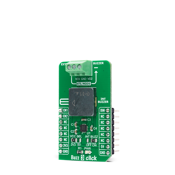
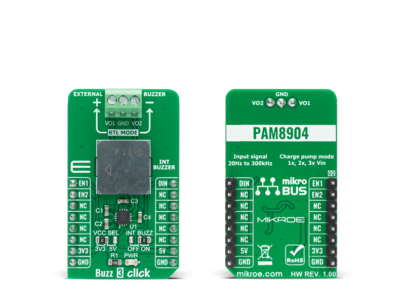
Buzz 3 Click is a compact add-on board that contains a sounder driver that produces higher volume with a lower current. This board features the PAM8904, a piezo-sounder driver with an integrated Multi-Mode charge pump boost converter from Diodes Incorporated.

No Abuse Reported

Do you want to subscribe in order to receive notifications regarding "Buzz 3 click" changes.

Do you want to unsubscribe in order to stop receiving notifications regarding "Buzz 3 click" changes.

Do you want to report abuse regarding "Buzz 3 click".

  • mikroSDK Library 2.0.0.0
  • Comments (0)
DOWNLOAD LINK RELATED COMPILER CONTAINS
mikroBasic PRO for ARM
  • lib
  • src
  • exa
  • hlp
  • hex
  • sch
  • pcb
  • doc
mikroBasic PRO for AVR
  • lib
  • src
  • exa
  • hlp
  • hex
  • sch
  • pcb
  • doc
mikroBasic PRO for dsPIC30/33 & PIC24
  • lib
  • src
  • exa
  • hlp
  • hex
  • sch
  • pcb
  • doc
mikroBasic PRO for FT90x
  • lib
  • src
  • exa
  • hlp
  • hex
  • sch
  • pcb
  • doc
mikroBasic PRO for PIC
  • lib
  • src
  • exa
  • hlp
  • hex
  • sch
  • pcb
  • doc
mikroBasic PRO for PIC32
  • lib
  • src
  • exa
  • hlp
  • hex
  • sch
  • pcb
  • doc
mikroC PRO for ARM
  • lib
  • src
  • exa
  • hlp
  • hex
  • sch
  • pcb
  • doc
mikroC PRO for AVR
  • lib
  • src
  • exa
  • hlp
  • hex
  • sch
  • pcb
  • doc
mikroC PRO for dsPIC30/33 & PIC24
  • lib
  • src
  • exa
  • hlp
  • hex
  • sch
  • pcb
  • doc
mikroC PRO for FT90x
  • lib
  • src
  • exa
  • hlp
  • hex
  • sch
  • pcb
  • doc
mikroC PRO for PIC
  • lib
  • src
  • exa
  • hlp
  • hex
  • sch
  • pcb
  • doc
mikroC PRO for PIC32
  • lib
  • src
  • exa
  • hlp
  • hex
  • sch
  • pcb
  • doc
mikroPascal PRO for ARM
  • lib
  • src
  • exa
  • hlp
  • hex
  • sch
  • pcb
  • doc
mikroPascal PRO for AVR
  • lib
  • src
  • exa
  • hlp
  • hex
  • sch
  • pcb
  • doc
mikroPascal PRO for dsPIC30/33 & PIC24
  • lib
  • src
  • exa
  • hlp
  • hex
  • sch
  • pcb
  • doc
mikroPascal PRO for FT90x
  • lib
  • src
  • exa
  • hlp
  • hex
  • sch
  • pcb
  • doc
mikroPascal PRO for PIC
  • lib
  • src
  • exa
  • hlp
  • hex
  • sch
  • pcb
  • doc
mikroPascal PRO for PIC32
  • lib
  • src
  • exa
  • hlp
  • hex
  • sch
  • pcb
  • doc

mikroSDK Library Blog

Buzz 3 click

Buzz 3 click

Native view of the Buzz 3 click board.

View full image
Buzz 3 click

Buzz 3 click

Front and back view of the Buzz 3 click board.

View full image

Library Description

The library covers all the necessary functions to control Buzz 3 Click board™. Library performs a standard GPIO interface communication.

Key functions:

  • BUZZ3_RETVAL_T buzz3_set_gain_operating_mode ( uint8_t op_mode ) - Set gain operating mode function.

Examples description

The application is composed of three sections :

  • System Initialization - Initializes GPIO, set AN and RST pin as outputs, begins to write a log.
  • Application Initialization - Initialization driver enables - GPIO and configures the appropriate MCU pin for sound generation, also write log.
  • Application Task - (code snippet) This is an example that demonstrates the use of the Buzz 3 Click board™. This example plays the Imperial March using the sound library. Results are being sent to the Usart Terminal where you can track their changes.
void application_task ( )
{
    mikrobus_logWrite( "   Play the music    ", _LOG_LINE );
    buzz3_melody( );
    mikrobus_logWrite( "---------------------", _LOG_LINE );
    Delay_ms( 1000 );
}


Additional Functions :

  • buzz3_sound_init( ) - Configures the appropriate MCU pin for sound generation.
  • buzz3_melody( ) - Demo melody - plays Imperial March using Sound library.

Other mikroE Libraries used in the example:

  • Sound
  • UART

Additional notes and informations

Depending on the development board you are using, you may need USB UART clickUSB UART 2 click or RS232 click to connect to your PC, for development systems with no UART to USB interface available on the board. The terminal available in all MikroElektronika compilers, or any other terminal application of your choice, can be used to read the message.

ALSO FROM THIS AUTHOR

RTC 17 click

0

RTC 17 Click is a compact add-on board that accurately keeps the time of a day. This board features the RV5C387A, a CMOS real-time clock with a built-in interrupt generation function from Nisshinbo Micro Devices Inc, to perform serial transmission of time and calendar data to the MCU. The BU9873 provides information like year, month, day, weekday, hours, minutes, and seconds based on a 32.768kHz quartz crystal through an I2C serial interface to transmit time and calendar data to the MCU. It also has an alarm function that outputs an interrupt signal to the MCU when the day of the week, hour, or minute matches with the preset time.

[Learn More]

Slider click

5

Slider click uses SPI bus communication to converts analog input voltage (VCC) to digital output value and shows this result on LED and USB UART terminal. Value of analog voltage depends on the slider position.

[Learn More]

Stepper 9 click

0

Stepper 9 Click is a compact add-on board that contains a bipolar stepper motor driver. This board features the TB67S581FNG, a two-phase bipolar stepping motor driver from Toshiba Semiconductor. Fabricated with the BiCD process, it supports a PWM constant-current control drive and steps resolution from full to 1/32 for less motor noise and smoother control. It has a wide operating voltage range of 8.2V to 44V with a maximum output current capacity of 2A, decay modes selection function, protection, and several anomaly detection indicators.

[Learn More]