TOP Contributors

  1. MIKROE (2663 codes)
  2. Alcides Ramos (358 codes)
  3. Shawon Shahryiar (307 codes)
  4. jm_palomino (112 codes)
  5. Chisanga Mumba (90 codes)
  6. S P (73 codes)
  7. dany (71 codes)
  8. MikroBUS.NET Team (35 codes)
  9. NART SCHINACKOW (34 codes)
  10. Armstrong Subero (27 codes)

Most Downloaded

  1. Timer Calculator (137081 times)
  2. FAT32 Library (70222 times)
  3. Network Ethernet Library (56094 times)
  4. USB Device Library (46413 times)
  5. Network WiFi Library (42031 times)
  6. FT800 Library (41375 times)
  7. GSM click (29109 times)
  8. mikroSDK (26555 times)
  9. PID Library (26487 times)
  10. microSD click (25486 times)
Libstock prefers package manager

Package Manager

We strongly encourage users to use Package manager for sharing their code on Libstock website, because it boosts your efficiency and leaves the end user with no room for error. [more info]

< Back
mikroSDK Library

Load cell click

Rating:

5

Author: MIKROE

Last Updated: 2019-11-14

Package Version: 1.0.0.0

mikroSDK Library: 1.0.0.0

Category: Force

Downloaded: 4839 times

Not followed.

License: MIT license  

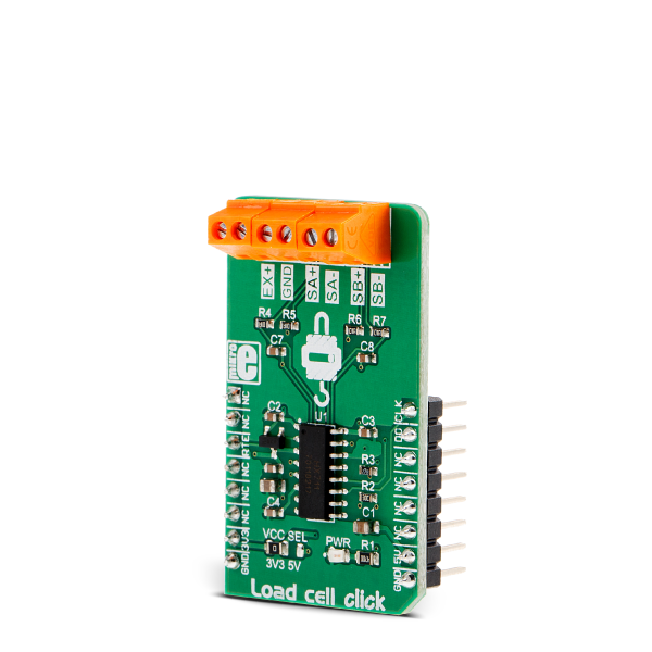
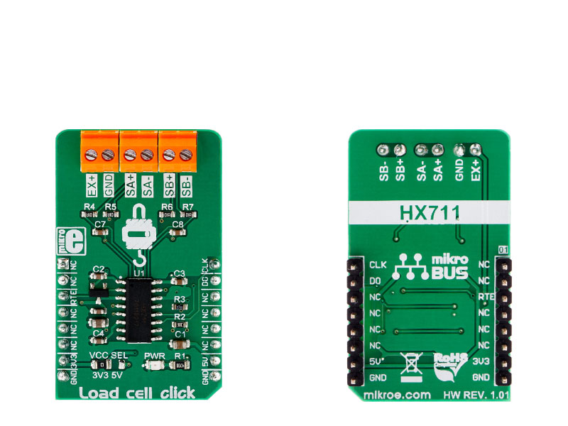
Load cell click is a weight measurement click which utilizes a load cell element, in order to precisely measure the weight of an object. The Load Cell click can be used with the strain gauge type of load cells and can measure up to ±20V or ±40V of differential voltage.

No Abuse Reported

Do you want to subscribe in order to receive notifications regarding "Load cell click" changes.

Do you want to unsubscribe in order to stop receiving notifications regarding "Load cell click" changes.

Do you want to report abuse regarding "Load cell click".

  • mikroSDK Library 2.0.0.0
  • Comments (0)
DOWNLOAD LINK RELATED COMPILER CONTAINS
mikroBasic PRO for ARM
  • lib
  • src
  • exa
  • hlp
  • hex
  • sch
  • pcb
  • doc
mikroBasic PRO for AVR
  • lib
  • src
  • exa
  • hlp
  • hex
  • sch
  • pcb
  • doc
mikroBasic PRO for dsPIC30/33 & PIC24
  • lib
  • src
  • exa
  • hlp
  • hex
  • sch
  • pcb
  • doc
mikroBasic PRO for FT90x
  • lib
  • src
  • exa
  • hlp
  • hex
  • sch
  • pcb
  • doc
mikroBasic PRO for PIC
  • lib
  • src
  • exa
  • hlp
  • hex
  • sch
  • pcb
  • doc
mikroBasic PRO for PIC32
  • lib
  • src
  • exa
  • hlp
  • hex
  • sch
  • pcb
  • doc
mikroC PRO for ARM
  • lib
  • src
  • exa
  • hlp
  • hex
  • sch
  • pcb
  • doc
mikroC PRO for AVR
  • lib
  • src
  • exa
  • hlp
  • hex
  • sch
  • pcb
  • doc
mikroC PRO for dsPIC30/33 & PIC24
  • lib
  • src
  • exa
  • hlp
  • hex
  • sch
  • pcb
  • doc
mikroC PRO for FT90x
  • lib
  • src
  • exa
  • hlp
  • hex
  • sch
  • pcb
  • doc
mikroC PRO for PIC
  • lib
  • src
  • exa
  • hlp
  • hex
  • sch
  • pcb
  • doc
mikroC PRO for PIC32
  • lib
  • src
  • exa
  • hlp
  • hex
  • sch
  • pcb
  • doc
mikroPascal PRO for ARM
  • lib
  • src
  • exa
  • hlp
  • hex
  • sch
  • pcb
  • doc
mikroPascal PRO for AVR
  • lib
  • src
  • exa
  • hlp
  • hex
  • sch
  • pcb
  • doc
mikroPascal PRO for dsPIC30/33 & PIC24
  • lib
  • src
  • exa
  • hlp
  • hex
  • sch
  • pcb
  • doc
mikroPascal PRO for FT90x
  • lib
  • src
  • exa
  • hlp
  • hex
  • sch
  • pcb
  • doc
mikroPascal PRO for PIC
  • lib
  • src
  • exa
  • hlp
  • hex
  • sch
  • pcb
  • doc
mikroPascal PRO for PIC32
  • lib
  • src
  • exa
  • hlp
  • hex
  • sch
  • pcb
  • doc

mikroSDK Library Blog

Load cell click

Load cell click

Native view of the Load cell click board.

View full image
Load cell click

Load cell click

Front and back view of the Load cell click board.

View full image

Library Description

The library covers all the necessary functions to control Load cell click board.
Library reads 24-bit digital converted results from the desired channel with determined rate value (which determines the frequency of internal oscillator).

Key functions:

  • float loadcell_get_weight ( uint8_t input_sel, loadcell_data_t *cell_data ) - Function performs measurement.
  • void loadcell_set_rate ( uint8_t rate_sel ) - Function selects the frequency of internal oscillator.
  • void loadcell_set_mode ( uint8_t pwr_mode ) - Function puts the device in Power Up or Power Down Mode.

Examples description

The application is composed of three sections :

  • System Initialization - Initializes peripherals and pins.
  • Application Initialization - Initializes GPIO driver and performs the device reset,
        after which the next conversion cycle will be for channel B with 32 gate value.
        This function also selects the frequency of the internal oscillator to 10Hz.
        Sets tare the scale, calibrate the scale and start measurements.
  • Application Task - (code snippet) - This is an example that demonstrates the use of Load Cell Click board.
        Display the measurement of scales in grams [ g ].
        Results are being sent to the Usart Terminal where you can track their changes.
        All data logs write on USB uart changes for every 1 sec.
void applicationTask()
{
    weight_val = loadcell_get_weight( LOADCELL_CHANN_B_GATE_32_NEXT, &cell_data );
    
    log_display( weight_val );
    
    Delay_ms( 1000 );
}

Additional Functions:

  • void log_display ( float display_val ) - The function displays readings as a floating-point value with two decimal places.

Other mikroE Libraries used in the example:

  • GPIO
  • Conversions
  • UART

Additional notes and informations

Depending on the development board you are using, you may need USB UART clickUSB UART 2 click or RS232 click to connect to your PC, for development systems with no UART to USB interface available on the board. The terminal available in all MikroElektronika compilers, or any other terminal application of your choice, can be used to read the message.

ALSO FROM THIS AUTHOR

BUZZ click

0

BUZZ Click is an accessory board in mikroBus™ form factor. Board features a piezo speaker capable of emitting audio signals.Buzzer’s resonant frequency is 3.8kHz (where you can expect it’s best performance).

[Learn More]

mikromedia 7 for STM32F7

1

Mikromedia 7 for STM32F7 is a compact development system with lots of on-board peripherals which allow development of devices with multimedia contents.

[Learn More]

LED Driver 13 click

0

LED Driver 13 Click is a compact add-on board that simplifies the control of multiple LEDs. This board features the A80604-1, a 4-channel LED driver designed at a switching frequency of 400kHz that provides 150mA per channel from Allegro Microsystems. It is powered by an external power supply in the range of 6V to 18V, providing an output voltage of approximately 26V, which is used to power LEDs connected to LED channels. On the logical side, this board uses both 3V3 and 5V with mikroBUS™ power rails and communicates with the MCU via GPIO pins. In addition, the user is given the option of analog or digital LED dimming selection, using a PWM pin from the mikroBUS™ socket or via an onboard potentiometer/external PWM signal.

[Learn More]